SciELO - Scientific Electronic Library Online

 
vol.66 número4Triggerless charge measurement system for fast characterization with avalanche photodiodes and photomultipliersGrowth and UV detector of serrated GaN nanowires by chemical vapor deposition índice de autoresíndice de materiabúsqueda de artículos
Home Pagelista alfabética de revistas  

Servicios Personalizados

Revista

Articulo

Indicadores

Links relacionados

  • No hay artículos similaresSimilares en SciELO

Compartir


Revista mexicana de física

versión impresa ISSN 0035-001X

Rev. mex. fis. vol.66 no.4 México jul./ago. 2020  Epub 31-Ene-2022

https://doi.org/10.31349/revmexfis.66.479 

Research

Material Sciences

Thermal properties and degradation kinetics of epoxy-γ -alumina and epoxy-zinc oxide lightweight composites

N. Camachoa 

J.F. May-Crespob 

J.B. Rojas-Trigosc 

K. Martínezc 

E. Marínc 

G.C. Mondragón-Rodríguezd 

aCONACYT-CIDESI-CENTA, National Center of Aeronautical Technologies, Carretera Estatal 200 Querétaro-Tequisquiapan Km. 23, No. 2254, Localidad Galeras, 76270, Parque Aeroespacial Querétaro. Colón, Querétaro, México. e-mail: nayeli.camacho@cidesi.edu.mx

bCONACYT -El Colegio de Michoacán, Cerro de Nahuatzen 85, Fracc. Jardines del Cerro Grande, La Piedad, Michoacán, 59370, México.

cInstituto Politécnico Nacional, CICATA-Legaria, Calzada Legaria No. 694 Col. Irrigación, Miguel Hidalgo, 11500, Ciudad de México, México.

dCONACyT, Center of Engineering and Industrial Development, CIDESI, Surface Engineering Department, Querétaro, Av. Pie de la Cuesta 702, 76125 Santiago de Querétaro, México.


Abstract

Lightweight composite materials are the gold standard in aeronautical and aerospace applications due to their strength and low mass. To transport higher payloads and reduce launching costs, nanosatellites, an excellent option for space exploration due to their lightweight structures, are migrating to composite materials. Nanosatellites, also known as CubeSats, must resist high thermal radiation loads while working in orbit. Polymer-based composite materials maintain low mass and the incorporation of reinforcing ceramic fillers contributes to increasing radiation and heat resistance, meeting both requirements. In this work, the effects of γ-alumina (Al2O3) and zinc oxide (ZnO) micro- and nanoparticles on the thermal properties and degradation kinetics of epoxy-based composites were investigated. The effective thermal conductivity improved up to 17.8 % for epoxy/γ-Al2O3 and 27.4% for epoxy/ZnO. The effective thermal diffusivity values show a monotonic decreasing behavior as a function of the particle concentration for the epoxy/γ-Al2O3 composites while for the epoxy/ZnO composites, no correlation on the effective thermal diffusivity values with the ZnO-content was observed. Both oxide-based ceramic fillers increase the thermal stability of epoxy up to 250oC; however, γ-Al2O3 decreased the maxima decomposition temperature of the epoxy matrix by 6oC. Zinc oxide did not affect the maxima decomposition temperature but decreased the activation energy of epoxy by 45%. These results provide a feasible manufacturing method for epoxy-based composite materials (i.e., nanosatellites) where efficient heat transfer, heat resistance, and low mass are required.

Keywords: Epoxy-based composites; oxide ceramic fillers; thermal stability; thermal conductivity

PACS: 61.46.+w; 65.80.+n; 74.25.Fy; 81.70.-q; 89.20.Kk

1.Introduction

In the last decades, nanosatellites, also called CubeSats, have transformed the landscape of space missions, especially for Earth orbit exploration. Nanosatellites have also been widely used as technology demonstrators, scientific tools, and for educational purposes [1,2,3]. The design of the nanosatellite structures considers minimizing the weight without sacrificing performance because it is technically convenient to accommodate higher payloads and to maintain or even reduce the cost of the launch. The recommended structural materials for the development of CubeSats - [3,4] - include Al-7075-T73 and Al-6061-T6 alloys, due to their strength, weight, and coefficient of thermal expansion [5]. Alternatively, a few scientific groups have started to explore the use of composite materials for the fabrication of the panels constituting nanosatellites [2,6], an example being the SwissCube, launched in 2009 [7], that included carbon fiber-epoxy composite panels in its structural subsystem. Composite materials have a lower density than aluminum alloys and represent a viable candidate to replace aluminum in some of the structural subsystems of the nanosatellites if thermal property requirements are met [8,9]. According to Corpino et al. [4], one of the most critical issues for nanosatellite missions is the effect of the thermal environment on the nanosatellite material. Heat transfer phenomena (direct solar radiation, albedo, earth infrared radiation (IR), and internal heat generation due to on-board electronics) in space are mainly regulated by thermal conduction and radiation [4]. Therefore, one of the most challenging issues is for the material to manage temperature variations ranging from 100oC to - 130oC corresponding to exposure to direct sunlight and eclipse phases in extremely short periods [1]. The current thermal properties of polymeric matrices used in the manufacturing of composite materials need to be improved to comply with the required standard for the construction of CubeSats.

Polymer-based composite materials reinforced with ceramic filler powders offer a diversity of possible multifunctional applications [10,11]. Several functional properties such as electrical conductivity, piezoelectricity, thermal conductivity, and thermal stability can be improved, with the addition of reinforcing particles [12]. Epoxy resins, used as the matrix of carbon fiber composites for aerospace, aeronautical, and automotive applications [13], have been combined with a variety of fillers at high and relatively low particle loadings such as graphene (1, 3, and 5 wt. %) [14], graphene oxide at 0.5 wt. % [15], carbon nanotubes at 1 and 6.1 wt. % [16,17], barium titanate at 6 wt. % [18], alumina from 1 to 70 wt. % [19-22] or combinations of these nanoparticles [17,23] to improve fracture toughness, electrical properties, flame retardancy, UV-shielding [24], and wear resistance [20]. Few studies have focused on the study of thermal properties. Y. Feng et al. [25] proved that the incorporation of Al2O3 particles induces an enhancement of the thermal conductivity of epoxy with increments of 145, 200, and 317 % at 50, 60, and 70 wt. % filler loading, respectively. M. Wasim Akhtar et al. also reported an increase in the thermal conductivity of epoxy with increasing filler loading up to 50 wt. % [26]. Both studies concluded that high particle loading (up to 70 wt. %) must be employed to obtain an apparent functional property improvement, which in turn, increases the weight of the material, decreases the specific mechanical properties, and turns the polymer fragile [22].

To design ceramic reinforced composite materials for nanosatellite structures, it is essential to improve the thermal properties (i.e., the thermal diffusivity and conductivity) of the epoxy resins without considerably increasing the weight of composite materials. The present investigation reports the effect of micro- and nanoparticle low concentrations <1 wt. % of γ-alumina (Al2O3) and zinc oxide (ZnO) on the thermal conductivity, stability, and kinetics degradation of an aeronautical grade biphasic epoxy resin system (Epolam 2500). The active thermography technique was employed to determine the thermal diffusivity at room temperature while the thermal conductivity of each composite was determined from the analysis of the transient thermal response. For each particle filler, the effect of the oxide nanoparticles on the thermal stability of the composite was assessed through degradation kinetics by thermogravimetric analysis.

2.Materials and methods

2.1.Particle preparation

The ZnO particles were prepared following the aqueous sol-gel synthesis method. Briefly, zinc acetate and oxalic acid were mixed at a molar concentration ratio of 0.1 /0.1 (M). The oxalic acid solution was added dropwise to the zinc acid solution, which was kept under constant agitation for 90 min (formation of the gel). The gel obtained was dried for 12 h at 60oC and then subjected to a thermal treatment at 600oC for 3 h.

The alumina particles were prepared by the citrate route. A polymeric citrate precursor derived from a citric acid aluminum nitrate solution at a molar concentration ratio of 0.5/0.1 (M) was used. The precursor thermal decomposition at 60oC formed a precipitate that was dried at 200oC for 2 h, followed by thermal treatment at 900oC for 2 h. The synthesized ZnO and Al2O3 particles were characterized in a SmartLab XRD diffractometer from Rigaku in PB/PSA mode Parallel Beam/Parallel Slit Analyzer with a grazing incidence angle (ω=0.5) 2θ geometry and Cu Kα radiation(40 kV, 44 Amp) at a step size of 0.04o. The diffraction patterns were indexed using the Integrated X-ray powder diffraction Software PDXL from Rigaku. The surface morphology of the synthesized powders was determined through a field emission scanning electron microscope (FE-SEM) Jeol JMS-7200F, using an accelerating voltage of 1.5 kV and different amplification factors.

2.2.Composite preparation

The resin compound Epolam 2500, a biphasic epoxy resin composed of primer and hardener was purchased from Sika Advanced Resins®. The primer and hardener were mixed at a 100:22 weight ratio. Zinc oxide or γ-Al2O3 particles were incorporated by solution blending in the epoxy resin at concentrations of 0.1, 0.25, and 0.5 wt. %. In a first step, ZnO particles were suspended in ethanol and sonicated for about 5 min to break the agglomerates as much as possible and until a homogeneous dispersion was achieved. Then, the epoxy resin was added to the solution that was kept under constant stirring at 50oC until ethanol was completely evaporated, and apparent uniform distribution of the ZnO in the resin was attained. The same mixing strategy was followed for the γ-Al2O3-epoxy composite. All samples were cured at room temperature for 24 h followed by a dwelling time of 2 h at 100oC.

2.3.Thermal characterization

2.3.1.Modulated thermal response

Thermal images were acquired through an active infrared thermography setup, consisting of a TTL controllable laser (120 mW LASER LDCU5, at 658 nm); a function generator, for the generation of the TTL control signal; a closed sample chamber; and an IR camera (FLIR, SC5000), suitable to operate in the 2.5 - 5.1 μm wavelength range. Between the IR camera and the sample chamber, a germanium window was placed to avoid undesirable contributions to the thermal images. The spherical lens is used to ensure a highly focused beam impinging on the frontal sample surface. Figure 1 displays a schematic of the active thermography system.

Figure 1 Schematic representation of the active thermography system. 

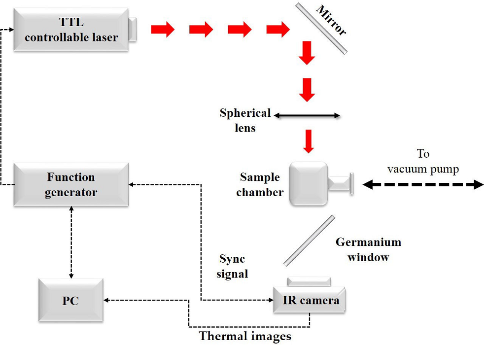
The capabilities of the IR camera electronics, along with its software, allow the phase-sensitive images processing and synchronization to the reference signal (from the function generator); so, there is no need for an external lock-in amplifier module. The sample chamber was kept at high vacuum (1×10⁻⁶ Torr) during the measurement using a rotatory vacuum pump (Varian Vacuum Technologies, DS 102) coupled with a turbo-molecular vacuum pump (Varian Vacuum Technologies, Turbo-V 81-AG) to avoid heat losses due to conductive and convective heat transfer to the surroundings. The modulation frequency of the excitation beam was fixed to 10 mHz.

2.3.2.Transient thermal response

The transient thermal response of each sample was sensed using a thermal analyzer (Hot-Disk), which employs a very thin nickel wire (shaped like a double spiral, encapsulated on a 25 μm-thick Kapton cover) as the transient plane source or TPS. The TPS functions as a heating source as well as a temperature sensor through its electrical resistance time-variations. These occur when a controlled electrical power, Pout, is sustained during the time measurement, tmeas, when the TPS is in thermal contact with the studied sample. This particular technique has some resemblance to the well-known Hot-wire and Hot-strip techniques, and their mathematical foundations can be found elsewhere [27,28,29]. To avoid heat losses through the boundaries of the sample as much as possible, a Pout=25 mW and a tmeas=10 s were considered.

2.3.3.Thermogravimetric analysis

The degradation kinetics of the composites were evaluated by thermogravimetric analysis (TGA), performed in a PerkinElmer® thermogravimetric analyzer (TGA 4000) in the temperature range from 50 to 900oC, in a nitrogen flow at 20 mlmin-1, at heating rates of 5, 10, 20 and 50oCmin-1. Pure epoxy samples and ZnO- and γ-Al2O3-epoxy composites were analyzed. Samples of 18.000±0.005 mg were placed inside the alumina sample-holder and then heated at a given heating ramp. The TGA analyses of the composites were performed under non-isothermal conditions; then, the activation energy of each composite was calculated with the Multilinear Regression Method (MLR) from the TGA data.

3. Results and discussion

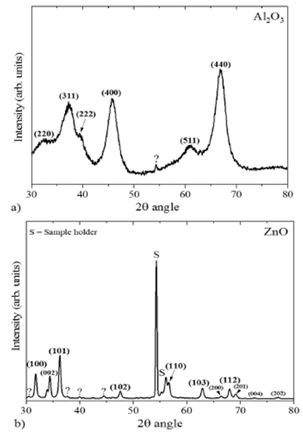
3.1.Ceramic-particles characterization

The acquired X-ray diffraction patterns of the γ-Al2O3 and ZnO synthesized particles are presented in Figs. 2a and 2b, respectively, identifying the characteristic XRD peaks with the Miller indices of their corresponding diffraction planes. While the ZnO particles exhibit sharp (Lorentz-type) peaks (Fig. 2b) corresponding mainly to the wurtzite hexagonal phase of ZnO; the XRD obtained for the γ-Al2O3 particles presents broader peaks (Fig. 2a), and their positions correspond predominantly to cubic γ-Al2O3 [30]. The observed peaks broadening is, presumably, due to the overlapping of Lorentz-type peaks. An estimate of the crystallite size was calculated using the Rietveld method. The crystallite size of γ-Al2O3 particles is about 3.32 nm, while the crystallite size for ZnO particles is 22.5 nm. The apparent morphology of the obtained particles was analyzed by FE-SEM micrographs (Fig. 3). The SEM micrographs show that the ZnO powders are a combination of rod-like structures with an average thickness of 63 nm and small cubic and irregular chunks, which seem to cohere in micrometric aggregates with a maximal averaged size of 20 μm in the powder form (Figs. 3c and 3e). On the other hand, the micrographs of the γ-Al2O3 particles show small irregular particles, as small as 50 nm and as large as 0.22 μm, which also present a tendency to form large aggregates in the powder form (Fig. 3d and 3f). Micrographs of the composites at a concentration of 0.5 wt. %, epolam/ZnO, and epolam/γ-Al2O3, are presented in Fig. 3a and 3b, respectively. As it can be observed on the micrographs, the particles are not visible on the surface of the composites, and the apparent surface roughness of the epolam /γ-Al2O3 is higher than that of the epolam/ZnO at this particle concentration.

Figure 2 X-ray diffraction pattern recorded for the (a) γ -Al2O3 and (b) ZnO synthesized particles. 

Figure 3 a) SEM micrographs of Epolam + 0.5 wt. % ZnO, b) Epolam + 0.5 wt. % γ -Al2O3, c) ZnO particles at 20kx, d) γ -Al2O3 particles at 10kx, e) ZnO particles at 80kx, and f) γ-Al2O3 particles at 80kx

3.2.Thermophysical Properties

The slope method for thermal diffusivity measurements shows that for a homogenous thermally thin, sample the following relationship exists:

mΔψmLn[rΔTac]=-ω2αeff, (1)

where Δψ is the photothermal phase shift; ΔTac is the (modulated) temperature amplitude; r is the radial coordinate; and mΔψ and mLn[rΔTac] are the slopes of the linear regions in the Δψ versus r and Ln[rΔTac] versus r curves, respectively [31,32,33,34,35]. From Eq. (1) the thermal diffusivity, αeff, can be obtained if the modulation frequency, ω is known. Figure 4 presents the Δψ vs. r and Ln[rΔTac] vs. r plots for the epoxy matrix. The convective-radiative heat losses at low frequencies are responsible for deviations from linearity [36].

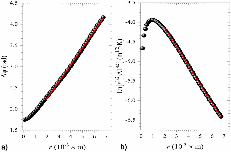
Figure 4 a) Δ ψ vs. r, and b) LnrTacvs. r plots, for the epoxy sample. The solid red line shows the best least-squares linear fit. 

Following the same data processing, the thermal diffusivity of the different epoxy/γ-Al2O3 and epoxy/ZnO composites was calculated; Figure 5 shows the results obtained. In any case, the error bars associated with the effective thermal diffusivity are one hundred times smaller than the αeff values (10-9 m2s-1) for the epoxy/Al2O3 composites. However, for the epoxy/ZnO composites, the variations of αeff as a function of the ZnO content are of the same order of magnitude of the corresponding error bars; therefore, the addition of ZnO has no real impact on the effective thermal diffusivity of such composite samples. On the other hand, the epoxy/γ-Al2O3 composites exhibit a non-linear monotonic decreasing behavior in αeff, with the γ-Al2O3 content. Figure 6 presents the transient thermal response of the samples under the experimental conditions described in 2.3.2 for different γ-Al2O3 and ZnO contents.

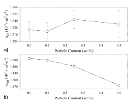
Figure 5 Obtained values for the effective thermal diffusivity, as a function of the particle content, for (a) Epoxy/Al2O3, and (b) Epoxy/ZnO composites. 

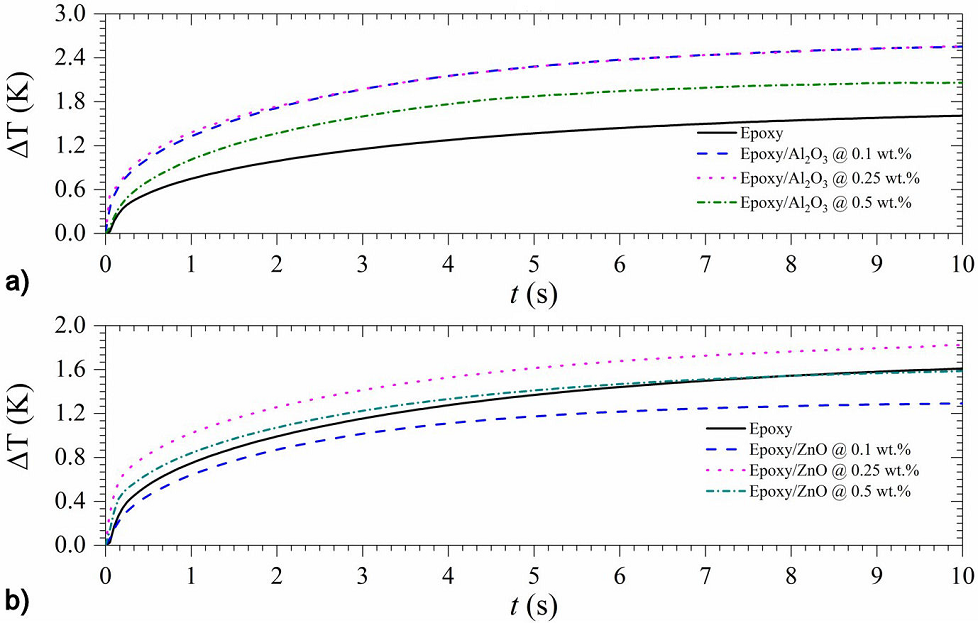
Figure 6 Thermal response (in amplitude) of a) Epoxy/Al2O3, and b) Epoxy/ZnO composites, recorded employing the Hot-Disk measurement system. 

The effective thermal conductivity, keff, of the composite samples was determined from the ΔT vs. t curves by linear fitting procedures according to the model reported by [29]. The obtained values for the neat epoxy matrix, epoxy/γ-Al2O3, and epoxy/ZnO composites agree well to similar epoxy-based composites reported elsewhere [32,33,26,37]. Figure 7 summarizes these results, indicating that the epoxy/γ-Al2O3 composites exhibit an increasing monotonic behavior for keff as a function of the γ-Al2O3 content, deviating from linearity at the origin. This supports that the oxide particle loading is well-dispersed within the matrix since dispersion has proven to be one of the most important factors to improve the thermal conductivity [26]. The improvement in thermal conductivity is recorded up to 17.8 % by introducing just 0.5 wt. % of γ-Al2O3. Furthermore, the improvement in thermal conductivity at such low oxide particle loading is similar to the improvement obtained by [26,47] filler loading up to 10 wt. % was added.

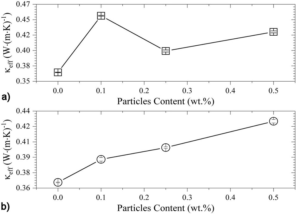
Figure 7 Effective thermal conductivity values of (a) Epoxy/Al2O3, and (b) Epoxy/ZnO composites, obtained from Hot-Disk measurement data. 

A quite different thermal behavior occurs for the epoxy/ZnO composites, were a non-monotonic dependency of keff on the ZnO content is evident. Moreover, the sample with 0.25 wt. % content of ZnO shows an important decrease in the keff value compared to the samples with 0.1 and 0.5 wt. % content of ZnO, but still higher than the keff value corresponding to the neat epoxy sample. Lower conductivity at this concentration could be due to agglomerate formation at this concentration.

Considering that keff, αeff are not independent thermophysical parameters, but related through the (effective) volume-specific heat capacity (also known as heat capacity per unit volume), Ceff=keffαeff-1. Figure 8 displays the calculated values of Ceff from this relation for all composite samples.

Figure 8 Calculated C eff values of a) Epoxy/Al2O3, and b) Epoxy/ZnO composites, as a function of the particle content. 

Again, the epoxy/γ-Al2O3 samples showed an increasing non-linear monotonic behavior in the Ceff values as a function of the γ-Al2O3 content. On the other hand, the epoxy/ZnO samples show that, for a 0.25 wt. % content of ZnO, Ceff has a local minimum mostly due to the effective thermal conductivity, since the effective thermal diffusivity values are practically the same for all the epoxy/ZnO samples here studied. Assuming that the synthesized γ-Al2O3 and ZnO particles are homogeneously distributed into the bulk of the sample, the effective volume-specific heat capacity could be estimated by Eq. (2) as follows:

Cbulk=ρrelw(d)C(d)+(1-w(d))C(m)1-(1-ρrel)w(p). (2)

In Eq. (2), C(m), C(d) are the volume-specific heat capacity of the continuous (neat epoxy matrix) and discrete phases (γ-Al2O3 and ZnO particles) of the composite, respectively; w(d) is the content fraction of the discrete phase, given by the wt. % particle content of the composite; and ρrel=ρ(m)ρ(d)-1 is the ratio of the mass densities. However, Eq. (2) has a decreasing behavior-owing to the thermophysical properties difference between the discrete and continuous composite phases-, contrary to the experimental observation for all composites. The observed demeanor of the thermophysical properties, αeff, keff, and Ceff- together with the theoretical estimation Cbulk-, suggest that the ballistic heat transfer mechanism competes with the diffusive heat transfer mechanism in response to the possible formation of axial thermal paths inside the composites, being the one exception, the epoxy/ZnO composite with 0.25 wt. %. For such a particular sample, it is plausible that the concentration of ZnO particles induces the agglomeration of the particles in disjoint volume elements, diminishing the formation of thermal paths and, therefore, a greater contribution of the diffusive heat transfer mechanism is observed. However, these hypotheses must be corroborated by quantification of the spatial distribution of the dispersed particles.

3.3.Thermal stability and degradation kinetics

The thermal stability of the epoxy/γ-Al2O3 and epoxy/ZnO was studied by TGA at a heating rate of 10oC/min under a nitrogen atmosphere. Figure 9 displays the thermograms and their derivative (DTG) obtained for epoxy/γ-Al2O3 and epoxy/ZnO, respectively. As a reference, neat epoxy without ceramic particle incorporation was also analyzed. From TGA curves (Figs. 9a and 9c) of the neat epoxy, it is possible to observe that the main thermal transition occurs from 250 to 500oC with a weight loss of about to 70 %, attributed to the degradation of the epoxy network [15]. A stable zone from 500 to 700oC follows this thermal transition, and a final weight loss of about 10 % occurs from 700 to 900oC.

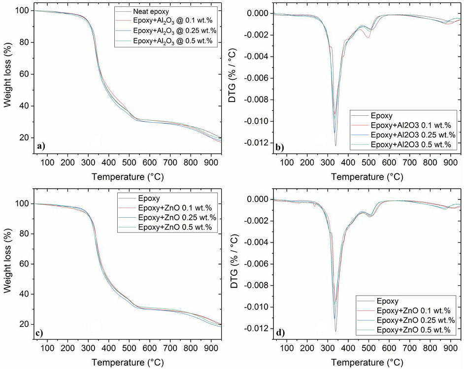
Figure 9 TGA thermograms for ceramic/epoxy and neat epoxy. The respective DTG thermograms for each concentration is displayed on the top right corner of the image. (a) Epoxy/Al2O3 and (b) Epoxy/ZnO. 

The total mass loss for all samples was ranged from 79.8 to 76.9 %. The derivative of the thermogravimetric curves helps to determine the temperature at which the maximum rate of thermal decomposition is reached (see Fig. 9). DTG curves displayed in Figs. 9b and 9d show a three-stage degradation for the neat epoxy in a nitrogen atmosphere, which is affected by the increasing content of each oxide. The first degradation stage of the epoxy starts at 314oC and is associated with uncured epoxy resin and loss of volatiles. The second stage of degradation onset was detected between 318 and 330oC with a maxima temperature decomposition at about 340oC; this points out to the decomposition of aromatic functional groups. The last stage observed between 480 and 550oC corresponds to the breaking of the main chains of the epoxy resin. These polymer degradation stages match with data reported in the literature [15,38,39].

The DTG curves for all composites showed that the addition of ceramic particles inhibited the first stage of the thermal degradation of epoxy, contributing to the dissipation of its volatile fraction. These findings have not been reported in other studies. The results demonstrate that for temperatures under 250oC, the addition of either ZnO or γ-Al2O3 with concentrations <1 wt. % increase the thermal stability of the epoxy matrix; this is in agreement with the analysis of volatile organic compounds in polymers reported elsewhere [40]. Similar thermal transitions were observed for the second and third stages of thermal decomposition for the neat epoxy, epoxy/γ-Al2O3, and epoxy/ZnO, as the transitions appear at similar temperatures ranges (318-330 and 480-550oC, respectively). However, for epoxy/γ-Al2O3 at a concentration of 0.1 wt. %, it was noted that the third transition shifts towards lower temperatures with an onset at about 455oC.

The incorporation of γ-Al2O3 decreases slightly the temperature at which the maximum rate of thermal decomposition occurs from 340 to 334oC, suggesting the detriment of the thermal stability of the matrix caused by the oxide. It is believed that γ-Al2O3, at low concentrations, acts as a catalyst at high temperatures, accelerating the breaking of the polymeric chains of epoxy resin and decreasing the decomposition temperature. In the case of ZnO incorporation, the DGT curves for all concentrations showed similar thermal behavior to neat epoxy, indicating the apparent conservation of the thermal stability of the matrix.

Thermal stability factors such as initial decomposition temperature (the temperature of 5 wt. % loss, Td5) and char at 900oC were determined for each composite. Table I lists the thermal stability factors for both composites at different filler content. The Td5 for epoxy/γ-Al2O3 at 0.1 and 0.25 wt. % was similar to that of neat epoxy. However, as the γ-Al2O3 content increased to 0.5 wt. %, the Td5 decreased by 15oC. For the epoxy/ZnO, the Td5 decreased by 19oC compared to neat epoxy, regardless of the particle content. The char at 900oC decreased for both composites compared to neat epoxy. Regardless of the ZnO particle content, the char at 900oC remains constant at 22.8 wt. % while a lower concentration of γ-Al2O3 displays the lowest char at 900oC, 20.20 wt. %.

Table I Thermal stability of epoxy/Al2O3 and epoxy/ZnO composites obtained from TGA thermograms. 

Filler Filler content
(wt.%)
Td5
(oC)
Char at 900oC
(%)
None 0 288 23.08
0.1 288 20.20
γ-Al2O3 0.25 288 20.20
0.5 273 21.34
0.1 269 22.80
ZnO 0.25 269 22.80
0.5 269 22.80

The thermal properties in this study are compared for epoxy resin-based composites produced by the above-mentioned process for particle loadings <1 wt. %. The comparability of the results obtained with other studies is restricted due to differences in the epoxy resin system used; for instance, Jiang et al. [21] studied the behavior of epoxy (DGEBA) with contents of nano alumina (α-Al2O3) from 1 to 4 wt. %; the results show the Td5 value of the composites similar to that of the neat epoxy resins (362.1oC) with char contents increasing gradually with increasing concentrations of nano Al2O3 [21]. Fan-Long Jin and Soo-Jin Park [41] studied the same epoxy resin system (DGEBA) with Al2O3 loadings ranging from 5 up to 15 wt. %; their results show a two-stage degradation process with char increasing as the concentration of Al2O3 was increased [41]. However, in our case, the char yield decreased for lower concentrations of alumina by 2.88 wt. % of the total mass used in the study compared to neat epoxy. The Td5 values remain the same until the alumina concentration reached 0.5 wt. %, at this point, the Td5 value decreased by 15oC.

Kinetic analysis of thermal degradation was carried out with Multilinear Regression (MLR) method to fit four data curves obtained at a constant heating rate by TGA in an inert atmosphere to the Arrhenius relationship, k(t)=Aexp(Ea/RT), determining the pre-exponential factor (A) (min-1), Ea is the apparent activation energy (kJmol-1), R is the universal gas constant, and T is the temperature (K). For the iso-conversion method, the expression for the rate of conversion dα/dT=k(T)[1-α]n can be used, where α is the degree of chemical conversion, n is the order of reaction, and k is the reaction rate. The three kinetic parameters have been obtained using various iso-conversion model-free as well as MRL methods from materials data as a function of temperature and conversion. Non-isothermal TGA is one of the best methods to understand the kinetics degradation process of polymers, therefore adequate to find solutions for the estimation of the kinetic parameters [42]. The degradation kinetics analysis at different heating ramps (5, 10, 20 and 50oC/min) showed a slight displacement towards higher temperatures with higher heating ramps for the neat epoxy resin and both composites (Fig. 10 and 11). This behavior is markedly observed at temperatures below 550oC for neat epoxy, 425oC for epoxy/γ-Al2O3 and 475oC for epoxy/ZnO.

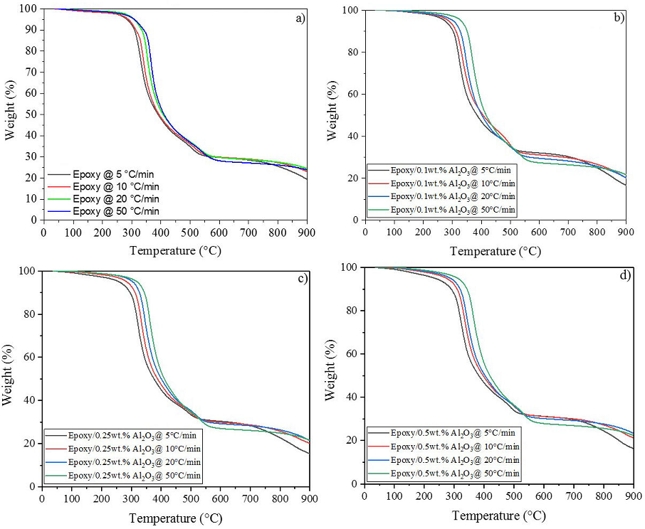
Figure 10 Thermograms of neat epoxy and Epoxy/Al2O3 at different heating ramps used to determine the kinetic degradation of the MRL method. a) Neat epoxy, b) 0.1 wt. %, c) 0.25 wt. %, and d) 0.5 wt. %. 

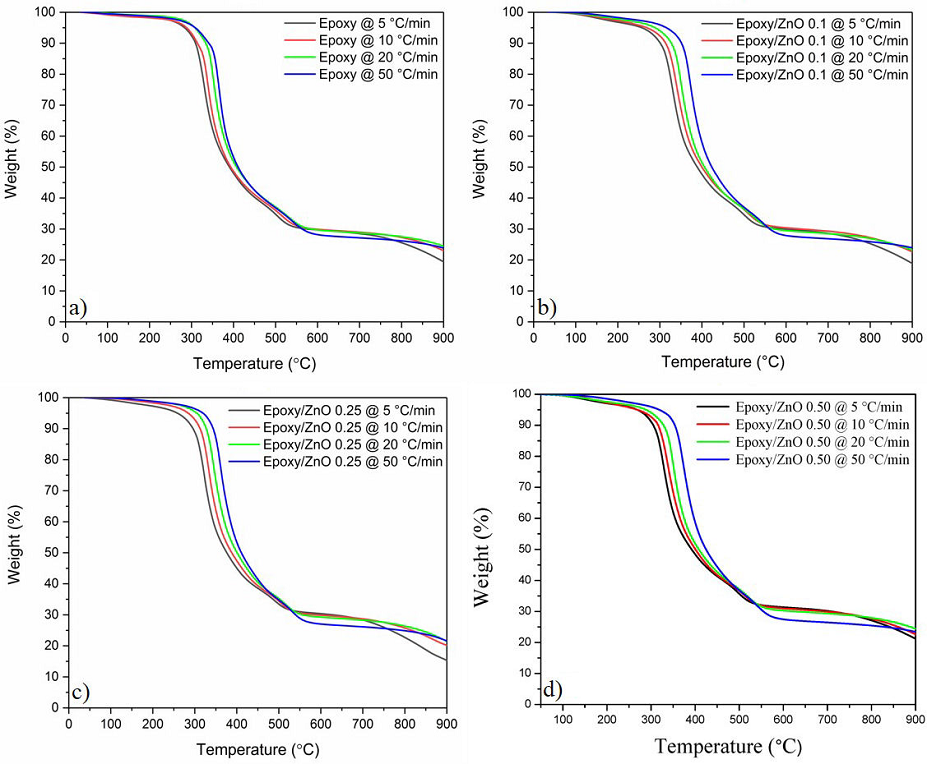
Figure 11 Thermograms of neat epoxy and Epoxy/ZnO at different heating ramps used to determinate kinetic degradation of MRL method. a) Neat epoxy, b) 0.1 wt. %, c) 0.25 wt. %, and d) 0.5 wt. %. 

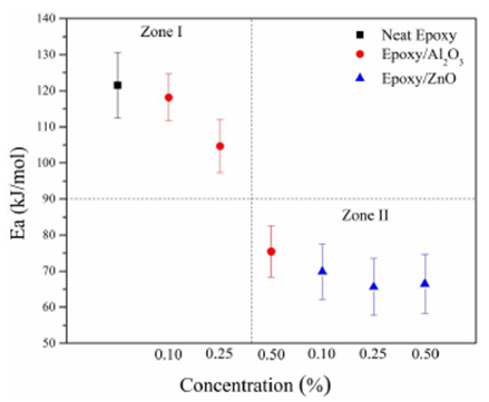
Figure 12 presents the activation energy (Ea) for all the composites and neat epoxy. Activation energy values were obtained with a determination coefficient (R2) at 95 % and taken conversions of (α) of 5, 10, 15, 20, 25, and 30 %. Ea of neat epoxy (121.53±9.15 kJ/mol) and epoxy/γ-Al2O3 @ 0.10 % and @ 0.25 % (118.11±6.47 and 104.63±7.34 kJ/mol, respectively) display similar values (Zone I). However, a significant decrease in Ea is observed for the γ-Al2O3 content of 0.50 wt. % (75.42±7.13 kJ/mol) (Zone II). These results are in agreement with the activation energy observed by Omrani and Rostami at a similar concentration of alumina (0.5 phr) [43]. Epoxy/ZnO composites, regardless of the concentration of the filler, show similar behavior to epoxy/γ-Al2O3 @ 0.5 %. These results suggest that loadings 0.5 wt. % of ZnO and only the loading of 0.5 wt. % of γ-Al2O3 decreased the thermal stability of neat epoxy resin. Other authors have reported decreasing activation energy values with the addition of oxide particles, mainly attributed to a catalytic effect of these particles [44,45,46]. This effect has been observed for copolymer/TiO2 [44] at a concentration of 0.2 wt. % and polyacrylate/ZnO (45) composites. Therefore, the incorporation of ZnO (for all cases) and Al2O3 at 0.5 wt. % had a significant impact on Ea values of neat epoxy.

Figure 12 Activation energy vs. nanoparticle concentration in wt. %. 

4.Conclusions

The present study analyzes the effect of the incorporation of low contents (0.1, 0.25, and 0.5 wt. %) of citrate route γ-Al2O3 and sol-gel synthesized ZnO nanoparticles on the thermal properties and degradation kinetics of Epolam 2500 epoxy resin. Concentrations under 1 wt. % of ceramic particles were introduced in the polymeric matrix to improve thermal behavior while maintaining the specific mechanical properties and low weight of the material.

The inclusion of γ-Al2O3 particles at loadings under 1 wt. % produces an evident competition between ballistic and diffusive heat transfer mechanisms, enhancing monotonically the thermal conductivity and volume-specific heat capacity of the composite as the nanoparticle content is increased at room temperature. For epoxy/ZnO, the dependence of the effective thermal conductivity on the concentration of zinc oxide particles is not monotonous. Similar behavior is obtained when calculating Ceff of the epoxy/ZnO. The experimental results suggest that in the samples with ZnO particle additions, the ballistic mechanism also dominates over the diffusive mechanism. However, when the ZnO content reaches 0.25 wt. %, agglomeration of the particles decreases the ballistic transport, altering the monotonous behavior for that concentration.

The incorporation of γ-Al2O3 and ZnO particles increased the thermal stability of the polymer up to 250oC, inhibiting the first stage of thermal decomposition of the epoxy. Above 250oC, the thermal decomposition of the epoxy was accelerated by the incorporation of γ-Al2O3, decreasing the temperature at which the maximum rate of thermal decomposition takes place by 6oC with particle loadings of 0.5 wt. %. The addition of ZnO particles decreases the initial decomposition temperature by 19oC in the second stage of the thermal degradation of epoxy, and the Ea value decreased by 45 %.

The results suggest that the incorporation of low loadings of alumina or oxide zinc nanoparticles increases the thermal properties and thermal stability of epoxy. These results also showed a feasible manufacturing method for lightweight epoxy-based composite materials that might be used for space applications (i.e. nanosatellites).

Acknowledgments

The authors kindly thank the Mexican Council of Science and Technology (CONACYT), the Cátedras Program and the Mexican Spatial Agency (AEM) for the financial support provided through the project 275783 “Diseño y caracterización de materiales compuestos para estructuras de nanosatélites tipo CubeSat”

References

1. E. Escobar, M. Diaz and J. C. Zagal, Appl. Therm. Eng., 105 (2016), 490. https://doi.org/10.1016/j.applthermaleng.2016.03.024 [ Links ]

2. C. E. Nomme, Mechanical Design of CubeSat Structures Using Composites and Polymers. Master Thesis, Institutt for produktutvikling og materialer. NTNU, (2013). [ Links ]

3. M. A. Silva, D. C. Guerreri, A. Cervone and E. Gill, Acta Astronaut., 143 (2018), 234. https://doi.org/10.1016/j.actaastro.2017.11.049 [ Links ]

4. S. Corpino, M. Caldera, F. Nichele, N. Masoero and N. Viola, Acta Astronaut. , 115 (2015), 247. https://doi.org/10.1016/j.actaastro.2015.05.012 [ Links ]

5. D. Arce, B. Jutzeler and G. Röthlisberger, Swiss Cube: Phase A Structure and Configuration (S3-A-STRU-1-4-Structure and Configuration), Haute École Specialisée de Suisse Occidental, LMAF (Lausanne, Switzerland, 2006). [ Links ]

6. A. Ampatzoglou, A. Baltopoulos, A. Kotzakolios and V. Kostopoulos, IJASAR, 1 (2014), 1. dx.doi.org/10.19070/2470-4415-140001 [ Links ]

7. École Polytechnique de Laussane, EPLF Space Center: SwissCube, (2011). [Online]. Available: http://swisscube.epfl.ch/Links ]

8. M. A. Viscio et al., Acta Astronaut. , 104 (2014), 516. https://doi.org/10.1016/j.actaastro.2014.06.005 [ Links ]

9. A. Poghosyan and A. Golkar, Prog. Aerosp. Sci., 88 (2017), 59. https://doi.org/10.1016/j.paerosci.2016.11.002 [ Links ]

10. N. Saba, P. Tahir and M. Jawaid, Polymers (Basel), 6 (2014), 2247. https://doi.org/10.3390/polym6082247 [ Links ]

11. S. Fakirov, Compos. Sci. Technol., 89 (2013), 211. https://doi.org/10.1016/j.compscitech.2013.10.007 [ Links ]

12. M. Baibarac and P. Gómez-Romero, J. Nanosci.Nano. Technol., 6 (2006), 289. https://doi.org/10.1166/jnn.2006.903 [ Links ]

13. X. Zhang, H. Hao, Y. Shi, J. Cui and X. Zhang , Constr. Build. Mater., 114 (2016), 638. https://doi.org/10.1016/j.conbuildmat.2015.04.057 [ Links ]

14. Y. Li, H. Zhang, H. Porwal, Z. Huang, E. Bilotti and T. Peijs, Compos. Part-A-Appl. S., 95 (2017), 229. https://doi.org/10.1016/j.compositesa.2017.01.007 [ Links ]

15. P. Katti, K. Kundan, S. Kumar and S. Bose, Polymer, 122 (2017),184. https://doi.org/10.1016/j.polymer.2017.06.059 [ Links ]

16. J. Kim, D. Seong, T. Kang and J. Youn, Carbon, 44 (2006), 1898. https://doi.org/10.1016/j.carbon.2006.02.026 [ Links ]

17. H.P. Chang, H. Liu, and C. Tan, Polymer, 75 (2015), 125. https://doi.org/10.1016/j.polymer.2015.08.023 [ Links ]

18. Wu, M., X. Yuan, H. Luo, C. Chen, K. Zhou and D. Zhang, Phys. Lett. A, 381 (19) (2017), 1641. https://doi.org/10.1016/j.physleta.2017.02.025 [ Links ]

19. Y. Hu, G. Du and N. Chen, Compos. Sci. Technol. , 124 (2016), 36. https://doi.org/10.1016/j.compscitech.2016.01.010 [ Links ]

20. L. McGrath, R. Parnas, S. King, J. Schroeder, D. Fischer and J. Lehart, Polymer, 49 (2008), 999. https://doi.org/10.1016/j.polymer.2007.12.014 [ Links ]

21. W. Jiang, F.-L. Jin and S.-J. Park, J. Ind. Eng.Chem., 18 (2012), 594. https://doi.org/10.1016/j.jiec.2011.11.140 [ Links ]

22. A. Omrani, L. Simon and A. Rostami, Mater. Chem. Phys., 114 (2009), 145. https://doi.org/10.1016/j.matchemphys.2008.08.090 [ Links ]

23. M. Zakaria, H. Akil, M. Kudus and M. Othman, Compos. Part B-Eng., 91 (2016), 235. https://doi.org/10.1016/j.compositesb.2016.01.013 [ Links ]

24. S. Mallakpour and V. Behranvand, Eur. Polym. J., 84 (2016), 377. https://doi.org/10.1016/j.eurpolymj.2016.09.028 [ Links ]

25. Y. Feng, C. He, Y. Wen, X. Zhou, X. Xie, Y. Ye and W.-W. Mai, Compos. Sci. Technol, 160 (2018), 42. [ Links ]

26. M. W. Akhtar, Y. S. Lee, D. J. Yoo and J. S. Kim, Compos. Part-B Eng., 131 (2017), 184. https://doi.org/10.1016/j.compositesb.2017.07.067 [ Links ]

27. S. Gustafsson, M. Chohan and A. Magsood, J. Appl. Phys., 55 (1984), 3348. https://doi.org/10.1063/1.333373 [ Links ]

28. A. Magsood and M. Anis-ur-Rehman, 2013IOP Conference Series: Materials Science and Engineering, Indus University, (Pakistan, 2013). [ Links ]

29. S. E. Gustafsson, Rev. Sci. Instrum., 62 (1991), 797. https://doi.org/10.1063/1.1142087 [ Links ]

30. G. Paglia, Faculty of Science, Department of Applied Physics and Department of Applied Chemistry, Curtin University, Perth, Australia, 2004. [ Links ]

31. J. Chiguma, E. Johnson, P. Shah, N. Gornopolskaya and W. Jones Jr., Open J. Compos. Mater ., 3 (2013), 51. https://doi.org/10.4236/ojcm.2013.33007 [ Links ]

32. Y.-X. Fu, Z.-X. He, D.-C. Mo and S.-S. Lu, Appl. Therm. Eng. , 66 (2014), 493. https://doi.org/10.1016/j.applthermaleng.2014.02.044 [ Links ]

33. W. Yuan, Q. Xiao, L. Li and T. Xu, Appl. Therm. Eng. , 106 (2016), 1067. https://doi.org/10.1016/j.applthermaleng.2016.06.089 [ Links ]

34. A. Mendioroz, R. Fuente-Dacal, E. Apiñaniz and A. Salazar, Rev. Sci. Instrum., 80 (2009), 074904. https://doi.org/10.1063/1.3176467 [ Links ]

35. A. Salazar , A. Mendioroz and R. Fuente, Appl. Phys. Lett., 95 (2009), 121905. https://doi.org/10.1063/1.3236782 [ Links ]

36. K. Martínez et al., Int. J. Therm. Sci., 98 (2015), 202. https://doi.org/10.1016/j.ijthermalsci.2015.07.019 [ Links ]

37. J. Gu, X. Yang, Z. Lv, N. Li, C. Liang and Q. Zhang, Int. J. Heat Mass Tran., 92 (2016), 15. https://doi.org/10.1016/j.ijheatmasstransfer.2015.08.081 [ Links ]

38. A. A. Moosa, F. Kubba, M. Raad and A. Ramazani, Am. J. Mater. Sci., 6 (2016), 125. https://doi.org/10.5923/j.materials.20160605.02 [ Links ]

39. D. Gúzman, X. Ramis, X. Fernández-Franco and A. Serra, Polymers, 7 (2015), 680. https://doi.org/10.3390/polym7040680 [ Links ]

40. K. Curran and M. Strlič, Stud. Conserv., 60 (1) (2015), 1. https://doi.org/10.1179/2047058413Y.0000000125 [ Links ]

41. F.-L. Jin andS.-J. Park , Polym. Degrad. Stabil., 97 (2012), 2148. https://doi.org/10.1016/j.jiec.2015.03.026 [ Links ]

42. M. Kumar, S. Sabbarwal, P. Mishra and S. Upadhyay, Bioresource Technol., 279 (2019), 262. https://doi.org/10.1016/j.biortech.2019.01.137 [ Links ]

43. A. Omrani and A. A. Rostami , Mat. Sci. Eng. A-Struct., 517 (2009), 185. https://doi.org/10.1016/j.msea.2009.03.076 [ Links ]

44. T.-K. Yang, S. S.-Y. Lin and T.-H. Chuang, Polym. Degrad. Stabil. , 78 (2002), 525. [ Links ]

45. S.-C. Liufu, H.-N. Xiao and Y.-P. Li, Polym. Degrad. Stabil. , 87 (2005), 103. https://doi.org/10.1016/j.polymdegradstab.2004.07.011 [ Links ]

46. M. Ghaffari, M. Ehsani, M. Vandalvand, E. Avazverdi, A. Askari and A. Goudarzi, Prog. Org. Coat., 89 (2015) 277. https://doi.org/10.1016/j.porgcoat.2015.08.016 [ Links ]

Received: January 17, 2020; Accepted: May 04, 2020

Creative Commons License This is an open-access article distributed under the terms of the Creative Commons Attribution License