1. Introduction
The space holder process (SHP) is a technique commonly used in metal foams production. It consists of three basic steps: (i) preparation of a removable preform, (ii) infiltration of the pattern with liquid metal, and (iii) removal of the pattern (Ashby et al., 2000; Banhart, 2001; Degischer & Kriszt, 2002; Gaillard et al., 2004). The SHP allows to obtain metallic foams from metals such as Zn, Ti, Fe and Ni and their respective alloys (Bach, Wilk, & Bormamm, 2003), metal glasses (Brothers et al., 2005), aluminum (Chou, & Song, 2002; Fernández et al., 2007) and magnesium (Lietaert et al., 2013; Trinidad et al., 2014).
Some authors indicate that an adequate preform must meet specific requirements; for instance, it must withstand high temperatures, preserve its form throughout the entire process, be easily removable at the end of the process to generate a porous structure, and be unreactive to the metal matrix. Different kinds of materials have been used as preforms in space holder processes (Fernández et al., 2008): polymeric particles (Ma et al.,1999; Shimizu et al., 2012), soft ceramics (Berchem et al., 2002), and carbamide particles (Bakan, 2006; Jiang et al., 2005). Other authors have used carbonates and fluorides such as K2CO3 (Zhao et al., 2005), NH4HCO3(Mondal et al., 2015), NaF (San Marchi et al., 2003), SrF2 and BaF2 (Brothers et al., 2005).
For manufacturing aluminum foams, preforms based on sodium chloride (NaCl) have been extensively used because of its high thermal resistance (melting point ~800°C), chemical stability, availability, and water solubility (Bach, Wilk & Bormamm, 2003; Gaillard et al., 2004; Pollien et al., 2005). All these characteristics make this material a good alternative to fabricate removable preforms at a relatively low cost, depending on the purity of the salt.
The use of NaCl has considerable advantages compared to polymeric or ceramic preforms (Fernández et al., 2008). There are different types of commercial salts used to fabricate the preforms, ranging from high purity (>99% NaCl) to refined and unrefined. The use of high-purity salt to manufacture metal foams is a common practice (Gaillard et al., 2004; Goodall et al., 2006), which increases the cost of the process and, hence, the final price of the obtained material. High-purity salt could be 40 times more expensive than refined salt, which is in turn around 10 times more expensive than unrefined salt. Nevertheless, there are still some unresolved questions about its use, mostly based on the assumption of possible negative effects on the metallic matrix from the points of view of the microstructure and corrosion (Bakan, 2006).
In this study, preforms made with refined and unrefined salt were used to produce open-cell aluminum foams. The influence of these preforms on the foams was studied in terms of the morphology of the porous structure, the microstructure of the metal matrix, and the corrosion rate evaluated under hydrodynamic conditions in an aqueous solution containing chlorides. In addition, differences were established between the refined and unrefined salt regarding their morphology, basic chemical composition, and dilution rate, leading us to propose the unrefined salt as a possible preform for manufacturing open-cell aluminum metal foams.
Finally, the resulting electrochemical characterization enabled us to evaluate the metal corrosion rate in the corrosion process of the solid aluminum base alloy as well as the foams. As a result, we can propose specific washing conditions to complete the removal phase in the SHP process.
2. Materials and methods
2.1. Manufacturing and characterization of aluminum metal foams
A granulometric analysis of the salts was conducted, and the particle size distribution of the sieved salt was evaluated using laser diffraction analysis in a Mastersizer 2000 system. A sample was taken from the salt particles with an average particle size of ~500 µm.
Morphological analyzes of the particles as well as semiquantitative elemental composition of the both salt samples were carried out using a JEOL model JSM-6490LV scanning electron microscope (SEM-EDS) at a voltage of 20 kV. Their solubility was measured using an automatic KRÜSS tensiometer with a Washburn cylinder accessory.
The SHP was used to obtain the foams as is described in (Navacerrada et al., 2013), and the preforms were fabricated with two different types of salt: refined and unrefined. Using an optical emission spectrometer Shimadzu model OES 5500, the chemical composition (%w) of aluminum alloy A356 used as the metal matrix is reported matrix was reported as follows: 7.24 Si, 0.40 Mg, 0.21 Fe, 0.014 Cu, 0.015 Mn.
The structural characteristics of the pores (such as morphology and size) were determined using a Micrometrics stereo microscope. The foam density, relative density, and porosity percentage were measured according to Eqs. (1) to (3) (Gibson & Ashby, 1997):
Where, the mass (m) and the volume (v) of the Al foam sample, and assuming the density of Al solid (δmaterial) = 2.70 g/cm3.
Based on the metallographic analyses, the phases present in the raw aluminum alloy and the microstructure of the aluminum alloy foam were established. The images were analyzed using Leica, Image J, and Micrometrics SE Premium software.
2.2. Electrochemical characterization
The electrochemical measurements were performed under hydrodynamic conditions and following the protocols previously established (Vásquez-Rendón et al., 2011; 2012). The polarization and chronoamperometric analyzes were performed in an AUTOLAB potentiostat (Metrohm Autolab B.V., Kanaalweg 29-G, 3526 KM Utrecht) using a common cell with three electrodes: a saturated calomel electrode as the reference electrode, a platinum mesh as the counter electrode, and a working electrode.
Two types of working electrodes were manufactured: (i) a rotating disk electrode (RDE), which comprised an A356 aluminum alloy bar fixed to a brass bar, and (ii) a porous rotating disk electrode (PRDE). In the latter, the assembly of the RDE was used to couple different samples of disk-shaped aluminum foams attached to a platinum disk that served as an electrical connection bridge between the foam and the RDE. Both electrodes were embedded in epoxy resin (SP 1840 A), as shown in Figure 1.
Commercial NaCl solutions with concentrations of 0.05 M and 0.5 M and pH values between 6.5 and 7, were prepared. The polarization curves were plotted at different rotation speeds: 10, 42, 94, 168, and 262 rad s−1. The potential scan was performed between -0.4 V and 0.6 V with respect to the open circuit potential (OCP) for solid aluminum, and between -0.5 V and 0.5 V with respect to the OCP for aluminum foams at a scan rate of 0.166 mV s-1.
The chronoamperometric measurements were performed based on previous studies (León, 2006; Pletcher et al., 2001; Revie, 2011). A fixed value of cathodic overpotential of −200 mV was used at electrode rotation rates ranging between 0 rad s−1 and 730 rad s−1, with a stabilization time of 8 min before each test. The resulting current values were evaluated according to the electrode rotation speed using Levich’s postulate in Eq. (4):
where
3. Results
3.1. Salt particles: Morphology and size
Figure 2 shows the representative cubic and irregular morphologies of refined and unrefined salt, respectively. The average grain size obtained by both laser and SEM techniques is around 500 μm. For the two kinds of salt examined (refined and unrefined), the analyzes were carried out at different points of the sample selected randomly, to obtain a representative collection of values that describe each kind of salt.
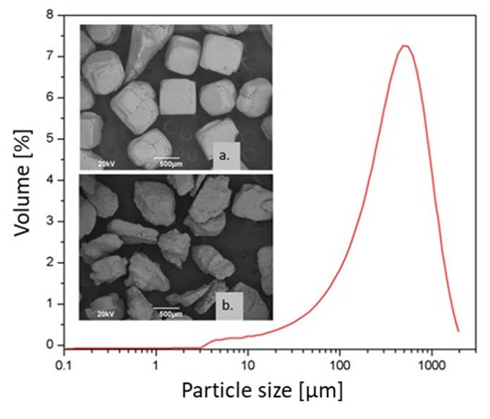
Figure 2 Particle size distribution of salt particles and SEM images of ~500 μm salt particles: a) cubic morphology (refined) and b) irregular morphology (unrefined).
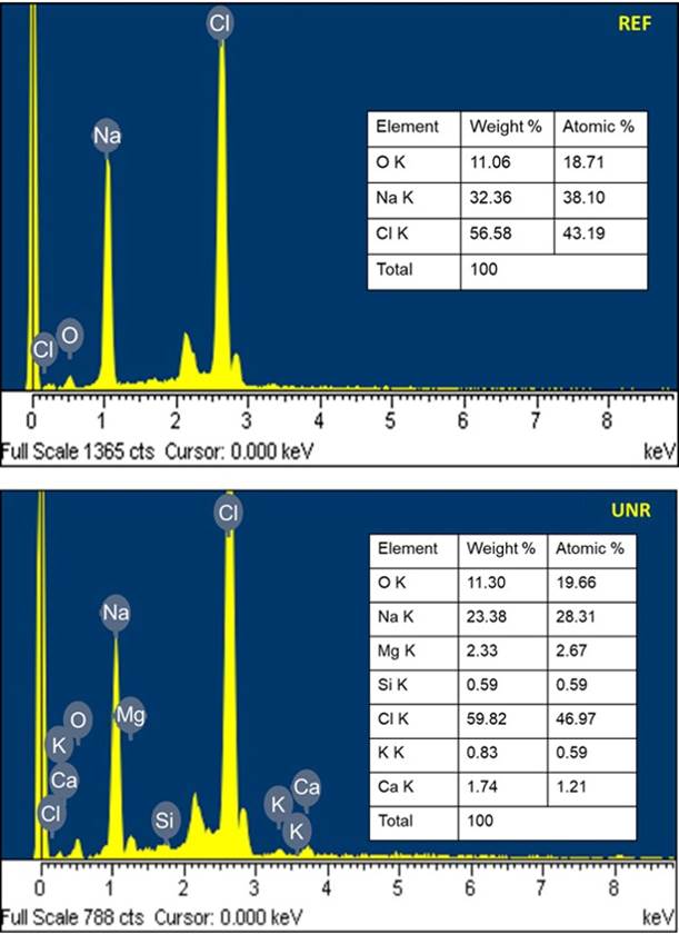
In Figure 3, a representative pair of elemental analysis EDS spectra of both salts are showed. In addition, the dissolution.rate..obtained..for..the..unrefined..salt..was.- 3.26 × 10⁻⁵± 4.86 × 10⁻⁸g s−1;….and..for..the..refined..salt,- 4.09 × 10⁻⁵± 3.38 × 10⁻⁷g s−1.
3.2 Structure and microstructure of aluminum foams
Figure 4 shows the porous structure of aluminum foams obtained with unrefined and refined salt preforms. The irregular morphology (unrefined) and cuasi-cubic morphology (refined), corresponding to pore sizes of 500 μm.
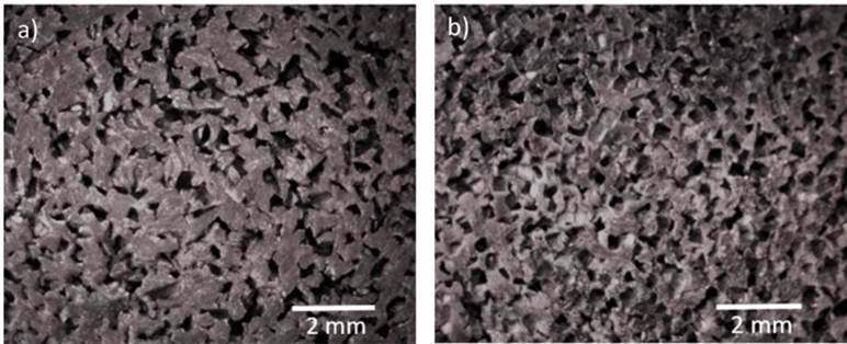
Figure 4 Pore morphologies of aluminum foam: a) irregular morphology (unrefined salt), b) cuasi-cubic morphology (refined salt). (Magnification: 0.7 X).
Figure 5 a-d shows the microstructure of raw A356 aluminum alloy, as well as in the metal foams obtained with both types of salt (refined and unrefined). It is noticed that raw alloy exhibits dendritic formations of rounded and agglomerated particles of Si (A) as dark gray spots inside the α(Al) matrix, together with black dispersed particles of Mg2Si (B) and α-FeSiAl particles as light-gray Chinese script (C).
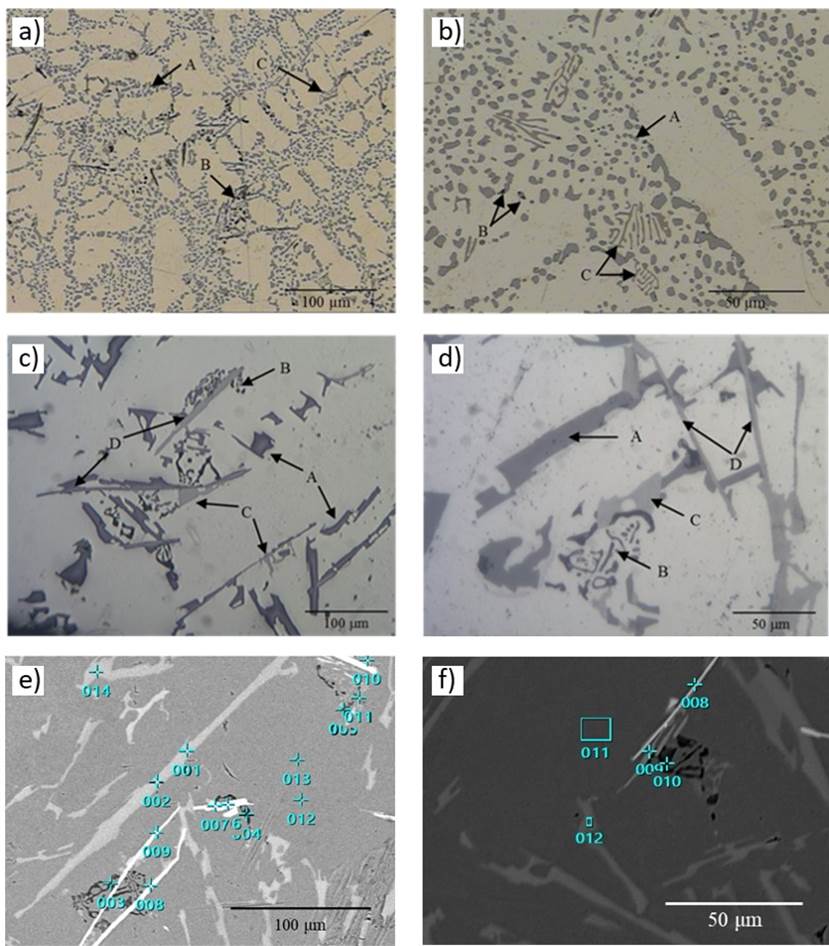
Figure 5 Microstructure of the A356 aluminum alloy: a-b) raw material, c) metal foam (refined salt), d) metal foam (unrefined salt), e) SEM image and EDS spots in metal foam (refined salt) and f) metal foam (unrefined salt).
The SEM image of metal foams microstructures presented in Figure 5 e-f are in good agreement with those obtained with optic microscopy. The aluminum foams exhibit coarse platelets shaped Si (A), Mg2Si as dark fine Chinese script (B), α-AlFeSi as Chinese script particles (C) and β-FeSiAl as light gray needles (D) Bray, 1990; (Warmuzek, 2004). The EDS spots highlighted in these images, are summarized in detail in Table 1.
Table 1 Elemental contents of EDS spots in Figure 5e-5f.
| Figure | EDS spot |
Mass fraction % | Microstructure | |||||
| Al | Si | Mg | Fe | Cu | Mn | |||
| 5e | 001 | 2.11 | 97.86 | 0 | 0 | 0.01 | 0.02 | Si |
| 004 | 63.71 | 12.38 | 23.88 | 0.03 | 0 | 0 | Mg2Si | |
| 006 | 63.81 | 10.70 | 0.12 | 24.77 | 0.23 | 0.37 | α-AlFeSi | |
| 008 | 74.69 | 11.89 | 1.55 | 11.77 | 0.03 | 0.07 | β-AlFeSi | |
| 013 | 98.10 | 1.57 | 0.33 | 0 | 0 | 0 | α-Al | |
| 5f | 008 | 73.34 | 13.30 | 0.48 | 12.78 | 0 | 0.10 | β-AlFeSi |
| 009 | 64.84 | 17.57 | 13.32 | 4.30 | 0 | 0 | α-AlFeSi | |
| 010 | 66.71 | 20.16 | 13.04 | 0.03 | 0.06 | 0 | Mg2Si | |
| 011 | 97.85 | 1.46 | 0.56 | 0 | 0.07 | 0.06 | α-Al | |
| 012 | 0.91 | 98.98 | 0.11 | 0 | 0 | 0 | Si | |
3.3. Polarization curves of the A356 Al alloy
Figure 6 a) shows the polarization curves of A356 aluminum alloy obtained for NaCl solutions at concentrations of 0 M, 0.05 M, and 0.5 M and rotation rate of 42 rad s−1. It can be noticed that increasing the concentration of chloride ions in the solution causes a shift in the corrosion potential Ecorr and the anodic current iAnod. However, the cathodic limit current iLimCat for the NaCl concentration of 0.5 M is below than that recorded by the NaCl concentration of 0.05 M. Figure 6 b) shows the effect of increasing the concentration of chloride ions ([Cl-] in parts per trillion) in an aqueous medium on the amount of dissolved oxygen present ([O2] in parts per million).
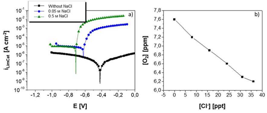
Figure 6 Effect of the increase in NaCl concentration on: a) the Ecorr and iLimCat values in polarization curves obtained at an electrode rotation speed of 42 rad s−1 and b) the solubility of O2 at different concentrations of Cl− at 25°C (data obtained from Table 45.2 in (Revie, 2011).
3.4. Corrosion rate of aluminum foams
In previous studies, (Vásquez-Rendón et al., 2011; 2012) concluded, based on results of polarization curves, that the anodic portion does not change with the increase in electrode rotation speed, contrary to what happens in the cathodic portion, in which there is a notable variation of the cathodic limit current, iLimCat.
Additionally, by performing experiments at different electrolyte pH values, we observed that the corrosion potential coincides with the pitting potential, Ecorr= Epit ≈ −0.7 V. It is known that electron transfer is measured in terms of current density, which is related to the reaction rate and the amount of reacting mass (loss of metal mass). Thus, using Eq. (5), we could determine the corrosion rate of the A356 aluminum and the foams in NaCl solutions:
where 0.129 is a constant of proportionality to obtain the corrosion rate in terms of mils per year (mpy); a, the atomic weight of the alloy (26.51 g mol-1); i, the current density (μA cm-2); n, the number of moles (3 mol); and D the density of the alloy (2.65 g cm-3). All the terms in the equation above can be obtained from the literature, except for the current density, which is determined from the corrosion current iCorr and the contact area of the working electrode using Eq. (6):
The corrosion current was obtained experimentally from the polarization curves using the extrapolation method of Tafel lines. The behavior of these polarization curves in the region of high cathodic overpotentials indicated that the cathodic current limit value iLimCat was the same as that of the corrosion current iCorr, as seen in Figure 6 a) for the two NaCl concentrations. Additionally, the surface area calculated for the RDE was 0.385 cm2, and, for analysis purposes, the foam area was considered with a unitary value of 1 cm2. Table 2 reports the current density and corrosion rate values of the A356 solid aluminum and the foams with a pore diameter of 0.5 mm in NaCl solutions at different concentrations and electrode rotation speeds.
Table 2 Corrosion current densities and corrosion rates of A356 aluminum in 0.05-M and 0.5-M NaCl solutions at different electrode rotation speeds.
| NaCl Concentration [M] |
Rotation Speed (ω) [rad s−1] |
Corrosion Current Density ( [μA cm-2] |
Corrosion Rate (r) [mpy] |
| Solid aluminum | |||
| 0.05 | 10 | 14.7±1.5 | 6.3±0.7 |
| 42 | 24.9±1.4 | 11.1±0.6 | |
| 94 | 35.0±1.5 | 14.7±0.7 | |
| 168 | 43.0±1.3 | 18.5±0.6 | |
| 262 | 58.8±0.8 | 25.4±0.4 | |
| 0.5 | 10 | 15.1±0.5 | 6.5±0.2 |
| 42 | 22.7±0.8 | 9.8±0.4 | |
| 94 | 25.5±0.3 | 11.0±0.1 | |
| 168 | 41.7±2.6 | 17.9±1.1 | |
| 262 | 46.6±1.1 | 20.0±0.5 | |
| Foams with a 0.5-mm pore diameter | |||
| 0.5 | 94 | 4.1±0.9 | 1.8±0.3 |
| 168 | 11.2±0.8 | 4.8±0.3 | |
| 262 | 261.9±22.0 | 112.7±9.5 | |
| 377 | 323.6±15.5 | 139.2±6.7 | |
| 513 | 377.6±19.5 | 163.1±8.4 | |
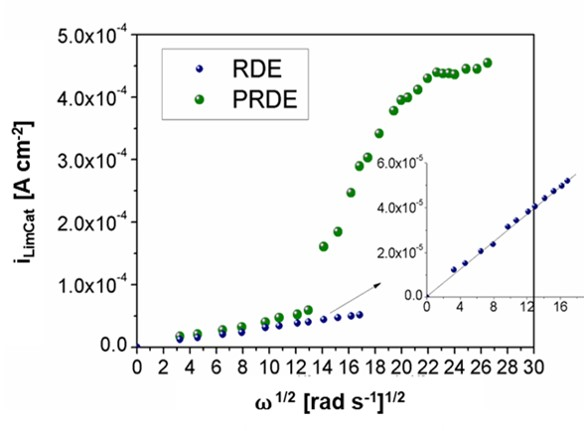
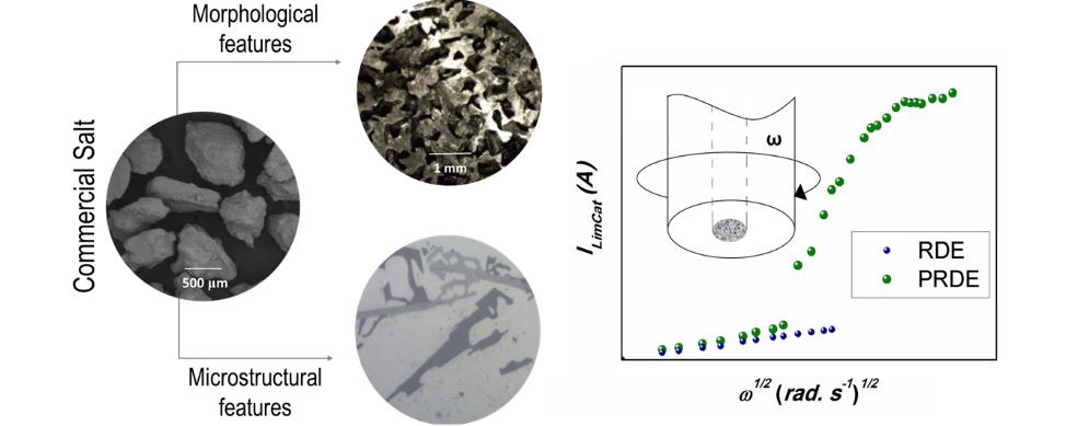
Figure 7 compares the iLimCat and ω1/2 curves of the RDE and PRDE obtained in steady state. It can be observed that, at low electrode rotation speeds between 3 (rad s−1)1/2- 13 (rad s−1)1/2, both electrodes exhibited a linear increase in the cathodic limit current as the electrode rotation speed rose. However, at a velocity of 14 (rad s−1)1/2, the current values of the porous electrode showed a significant increase, which deviated from the linear behavior predicted by Levich, Eq. (4).
4. Discussion
It should be noted that the EDS results show a heterogeneous distribution of Na and Cl in both types of salt. In addition, unrefined salt there shows additional elements such as Mg, Ca, in addition to K and Si (the latter could be related to traces of sand in the salt). It should be noted that because we use powders instead of flat samples and do not calibrate with standards for each of the elements, we cannot carry out a rigorous quantitative analysis (Alomary, 2012). However, these semi-quantitative results of the EDS elemental analysis allow us to observe that the unrefined salt presents additional elements as expected (Kuisma‐Kursula, 2000), which certainly promotes a different behavior. For example, refined salt dissolves one gram per second faster than its unrefined counterpart, which means that using unrefined salt would imply a longer time to remove it from the metal foam. However, the necessary time to complete its dissolution is not as long as to discard its use.
Regarding salt purity, some authors have reported the importance of using high-purity and even ultra-high purity salt (Despois et al., 2007; Goodall et al., 2006). Nevertheless, no relevant differences between refined and unrefined salt have been reported to justify the use of high purity over refined and unrefined salt.
Despite of the purity level of the salts, high-purity and ultra-high purity can result in different morphologies and pore sizes, as reported by (Jinnapat & Kennedy, 2010), who included spherical particles; and (Gaillard et al., 2004) who used cubic, hollow cubic, and irregular particles. In contrast, the size of the salt particles does not represent an important point in terms of the type of salt used in the preform, since it will simply be selected by a sieving process and according to the desired pore size in the metal foam. As reported by Casolco, et al. 2005, a metal foam porous structure will be a replica of the size and morphology of the salt particles in the preform, which can be used to control these parameters.
At a microstructural level, for both metal foams can be observed the presence of α-AlFeSi together with β-AlSiFe phase, and even though the presence of phases such as Si and Mg2Si remains, they occur in different morphologies. This may be attributed to differences in the cooling rate during the solidification process of the foams, compared to that of raw material (Andoko et al., 2020; Baskaran et al., 2021; Gecu et al., 2018; Kashyap & Chandrasekhar, 2001; Mohamed & Samuel, 2012).
Concerning Si, a possible modification of the grain can be suggested due to the presence of Na in the salt preform. As reported by Shankar et al. 2004, for unmodified alloys Si crystals are generally in platelike forms, just as those observed in the microstructures in Figure 5. It could be possible that in the metal foams, the interaction between A356 aluminum alloy with each type of salt preforms leads to some changes in the microstructure. According to (Dighe et al., 2002; Gokhale & Patel, 2005), NaCl acts somehow as a morphology modifier of Si phase in Al-Si-Mg aluminum alloys. The result is a fibrous Si structure commonly known as “coral”. In general, the treatment with Na is essential to inhibit Si crystals growth and to modify their morphology. In this type of alloys, sometimes Na traces are desirable and tolerable since they offer intermediate mechanical properties.
With respect to the polarization curves of the A356 alloy in an aqueous medium with chlorides, Figure 6 a) shows that, with a solution free of chloride ions (Cl−), the corrosion potential is more positive (nobler) than that with the two other solutions, and that the corrosion current is much lower compared to that obtained with solutions containing NaCl. This behavior is to be expected, since it is known that the Cl− content in the solution stimulates aluminum corrosion. As the Cl− concentration increases, the corrosion potential shifts to more negative values, which indicates that the metal becomes more electrochemically active. Also as expected, at high anodic polarizations, the anodic current is higher when the concentration of chloride ions increases.
However, when the cathodic currents of the two NaCl solutions are compared, a peculiar behavior can be noticed. Vásquez-Rendón et al. explained that the increase in the chloride ion content causes a slight decrease in the cathodic limit current, which translates into a lower corrosion rate since the oxygen reduction reaction is governing the aluminum corrosion reaction (Vásquez-Rendón et al., 2011; 2012). This situation is explained from the point of view of the dissolved oxygen concentration in the solution, and how it is affected by the variation in NaCl concentration. Revie and Mel’nichenko agree in that, by increasing the concentration of chloride ions in an aqueous medium, the amount of dissolved oxygen in the solution decreases, just as shown in Figure 6 b) (Revie, 2011; Mel’nichenko, 2008).
The corrosion phenomena that occur on the metal-electrolyte interface depend entirely on the conditions of the medium under which tests are performed (including pH, NaCl concentration, and dissolved oxygen). (Vásquez-Rendón et al., 2011; 2012) observed that the variation in the rotation speeds of the electrode has an effect only on the cathodic limit current. (During, 2018) pointed out that the reduction reactions that take place in the cathodic branch occur at a lower speed, and, as known thanks to reaction kinetics, the slowest reaction in an electrochemical process is that which controls the overall process. That means that the dissolved oxygen in the solution has a significant effect on the corrosion phenomenon of the metal. This is particularly important for the resulting technical application since it implies that, if A356 aluminum foams are washed with an electrolyte (water) with a low oxygen concentration, a decrease in the corrosivity of the medium would be expected and, therefore, a lower corrosion rate of the metal. However, during the washing stage of the SHP the water contains oxygen. Consequently, the effect of flow rate on the corrosion rate of the metal must be further evaluated in future studies.
About the corrosion rate of aluminum foams, (Vásquez-Rendón et al., 2011; 2012) reported that the shape of the polarization curves in the region of high cathodic overpotentials indicates that the cathodic limit current value, iLimCat, is the same as that of the corrosion current iCorr. Because the corrosion current iCorr is directly linked to the corrosion rate r, it is possible to relate the cathodic iLimCat values to the corrosion rate calculated by electrochemical techniques. Additionally, the remarkable variation of the cathodic limit current iLimCat with the increase in rotation speed indicates that, only in this region, such current is controlled by diffusion or mass transport. The latter is directly affected by the arrival speed of electroactive species to the metal surface (in this case, dissolved oxygen in the solution).
Table 2 shows that, in the case of solid aluminum in contact with both NaCl concentrations, higher electrode rotation rates increase the current density and, hence, the corrosion rate of the metal. However, the corrosion current values are slightly high for the 0.05 M NaCl concentration. This is explained by the phenomenon described in Figure 6 b), in which the decrease in the amount of oxygen available on the metal surface causes a slight decrease in the corrosion current. Since the oxygen reduction reaction determines the corrosion rate of aluminum in a chloride medium, if it decreases, so will the corrosion rate.
The corrosion rate values of the foams differ considerably from those of the solid aluminum. At a NaCl concentration of 0.5 M and low rotation speeds (94 rad s−1-168 rad s−1), the corrosion rates of the foams reach 1.8 mpy-4.8 mpy, which is lower than that of solid aluminum at the same rotation speed (18.5 mpy). However, by increasing the electrode rotation speed to 262 rad s−1, the corrosion rate of the foams was substantially accelerated, multiplying it by almost five times.
Morgan classified the corrosion resistance of aluminum exposed to aqueous solutions with chlorides (sea water) with respect to the corrosion rate r as follows: r < 1.97 mpy, excellent; 1.97 mpy < r < 3.94 mpy, good; 3.94 mpy < r < 7.87 mpy, acceptable; 7.87 mpy < r < 11.8 mpy, poor; and r > 11.8 mpy, unacceptable (values of r reported in milli-inch per year, mpy) (Morgan, 2020). Comparing these values with the results in Table 2, it can be concluded that the corrosion rate values of the A356 aluminum, determined at electrode rotation speeds ranging from 10 rad s−1 to 42 rad s−1, fall within a corrosion resistance range from acceptable to poor. Moreover, at rotation speeds greater than 42 rad s−1, the corrosion rate values of aluminum are considered unacceptable because they are close to or exceed 11.8 mpy. This comparison gives us an idea of the acceptable corrosion rate ranges of aluminum and its alloys to use in certain applications. In this study, it was useful to define the optimal washing conditions for aluminum foams obtained with salt preforms.
Regarding the foams, their corrosion rate values at low electrode rotation speeds (<168 rad s−1) can be said to achieve between excellent and good levels of acceptability. These results indicate that it is possible to wash the salt to obtain aluminum foams using hydrodynamic conditions, but always considering that these flow rates must be low to ensure that their structural integrity is not compromised at any stage of the process due to corrosion. The above can be explained more clearly by the correlation between the cathodic limit current and the rotation speed using the Levich equation for both types of electrodes.
The results of the chronoamperometric measurements allowed us to obtain the limit current values under potentiostatic conditions. Figure 7 reveals a sigmoidal behavior of the iLimCatvs. ω1/2 curve of the porous electrode, which is attributed to the effects of mass transport within a porous electrode. When the tests were conducted at low rotation speeds, the PRDE behaved similar to the RDE. However, by gradually increasing the rotation rate, the electrolyte infiltration into the foam pores became more effective and the corrosion current increased sharply until it stabilized at high rotation rates. These results are consistent with those reported by Bonnecaze et al. (2006), who evaluated the effect of hydrodynamics on the electrochemical behavior of porous carbon fiber electrodes in a 1 mM potassium iodide solution (Bonnecaze et al., 2006).
5. Conclusions
Using salts to produce metal foams provides benefits such as the generation of uniform and replicable porous structures in terms of morphology and microstructural behavior, as well as the presence of phases that generally induce a better mechanical behavior in the material.
The results obtained in this study from processing aluminum foams using the space holder method allowed us to establish the optimal conditions for the salt removal technique, especially to determine the flow rate for the washing processes under hydrodynamic conditions. With respect to the influence of the salt preform (NaCl) on the aluminum alloy foam, there was no evidence of corrosion, and, although a microstructural modification was observed, it was not considered relevant for the mechanical, physical, or structural behavior of the aluminum foams.
In that sense, given its widespread availability, high thermal resistance, easy removal using running water, and low cost, common salt turns out to be an attractive alternative as a preform for producing aluminum foams. This boosts the potential of metal foams because they can be manufactured at a low cost and marketed for the applications they currently have, including sound acoustic absorption plates, vibration dampers, diffusers, filters, and heat exchangers.


 nova página do texto(beta)


