


Serviços Personalizados
Journal
Artigo
 texto em
  Inglês (pdf)
 Artigo em XML
 Referências do artigo
 Enviar este artigo por email
Indicadores
-
 Citado por SciELO
 -
 Acessos
Links relacionados
-
 Similares em
SciELO
Similares em
SciELO
Compartilhar

 Permalink
Revista ALCONPAT
versão On-line ISSN 2007-6835
Rev. ALCONPAT vol.7 no.3 Mérida Set./Dez. 2017
https://doi.org/10.21041/ra.v7i3.240
Applied research
Methodologies for locating damage in prestressed concrete beams
1 Departamento de Ingeniería, Universidad Nacional del Sur, Argentina.
2 Consejo Nacional de Investigaciones Científicas y Técnicas, Argentina.
3 Comisión de Investigaciones Científicas de la Prov. de Buenos Aires, Argentina.
This work evaluates methodologies for the detection of damage in prestressed concrete structures. The methods studied are the variation of the displacements and the curvature of the elastic, complemented by the use of thermographic images. To this end, these methods were applied on two prestressed concrete beams, built in the laboratory. The results obtained allowed to detect the presence of damage and to locate it with good precision. Although these methods have already been applied to reinforced concrete structures, no applications have been found to prestressed concrete structures. The effectiveness of the proposed methodologies was demonstrated and the possibility and convenience of a combined use of them are highlighted.
Keywords: prestressed concrete; crack detection; static tests; displacements; elastic
En este trabajo se evalúan metodologías para la detección de daño en estructuras de hormigón pretensado. Los métodos estudiados son el de variación de los desplazamientos y el de curvatura de la elástica, complementados con el uso de imágenes termográficas. A tal fin, dichos métodos se aplicaron sobre dos vigas de hormigón pretensado, construidas en laboratorio. Los resultados obtenidos permitieron detectar la presencia de daño y localizarlo con buena precisión. Si bien estos métodos ya se han aplicado sobre estructuras de hormigón armado, no se han encontrado aplicaciones sobre estructuras de hormigón pretensado. Se demostró la efectividad de las metodologías propuestas y se destaca la posibilidad y conveniencia de un uso combinado de las mismas.
Palabras clave: hormigón pretensado; detección de fisuras; ensayos estáticos; desplazamientos; elástica
Em este trabalho são avaliadas metodologias para a detecção de danos em estruturas de concreto protendido. Os métodos estudados são a variação dos deslocamentos e a curvatura da elástica, complementados com o uso de imagens termográficas. Para este fim, tais métodos foram aplicados em duas vigas de concreto protendidas, construídas em laboratório. Os resultados obtidos permitiram detectar a presença de dano e localizá-lo com boa precisão. Embora esses métodos já tenham sido aplicados em estruturas de concreto armado, não foram encontradas aplicações em estruturas de concreto protendido. A eficácia das metodologias propostas foi demonstrada e a possibilidade e a conveniência de um uso combinado delas são destacadas.
Palabras clave: concreto protendido; detecção de fissuras; ensaios estáticos; deslocamentos; elástica.
1. INTRODUCTION
Prestressed concrete is a material very used in the construction industry, being the structural typology of straight-axis beams one of its most common uses. These structures often suffer various types of damage throughout their service life, so it is extremely important to identify them, as far in advance as possible, for the purpose of taking subsequent interventions.
The pathologies that may be present in prestressed concrete structures are varied; however, as in any concrete structure, the most common manifestation of them is through the appearance of cracks. This has led to several studies about the cracking of prestressed concrete, in different ages and for various causes (Karayannis y Chalioris, 2013; Dai et al., 2016; Tong et al., 2016).
Although, in many cases, a concrete structure with cracks may keep its structural function, depending on the stage of the damage and its speed of propagation; the mere presence of such cracks deserves attention, since they may involve a potential risk to the structure safety. In addition, in a cracked concrete structure (reinforced or prestressed), it is facilitated the access of corrosive agents that can reach the steel, with the aggravating factor, in the case of prestressed, that the steel is much more sensitive to the corrosion under tension (Bertolini et al., 2014).
One particular feature of prestressed concrete structures, compared to reinforced concrete structures, is that the prestressing action tends to keep the cracks closed, once the cause that originated them has disappeared. This makes difficult the visual inspections of the structure, as a first general diagnosis. In this way, arises the need of developing and/or validate methods that allow inspecting the health of structures, in order to first detect the presence of damage, then locate it and if possible quantify it.
In the present work two methods of diagnosis, based on the static response of the structure and applied specifically to the detection of cracks by flexion, are studied in prestressed concrete beams. These methods are known as displacement variation method (DVM) and elastic curvature method (ECM). The implementation of these methods was carried out on two prestressed concrete beams, constructed in the laboratory.
The mentioned methods have been studied by several authors, among which the works of (Pandey et al., 1991; Lu et al., 2002; Domínguez et al., 2007; Orbanich et al., 2009; Robles et. al., 2011; Dawari y Vesmawala, 2013; Ercolani et al., 2015). However, no applications of such methods have been found on prestressed concrete structures.
2. EXPERIMENTAL METHODOLOGY
The laboratory tests were carried out on two beams of similar characteristics but damaged in two different positions: The Beam 01 in the central zone and the Beam 02 in a position close to one of the supports. The damages consisted of a discrete crack caused by the application of a point load.
2.1 Characteristics of the beams tested
The beams are composed of a precast concrete joist, of T section, to which a compression head of in situ concrete has been added, resulting in a beam of rectangular section. In order to obtain good adhesion between the in situ concrete and the precast concrete, an epoxy bonding was used. The total length of the beams is 2.20 m. The trajectory of the prestressed steel is straight. The cross-section of the beams is shown in Figure 1.
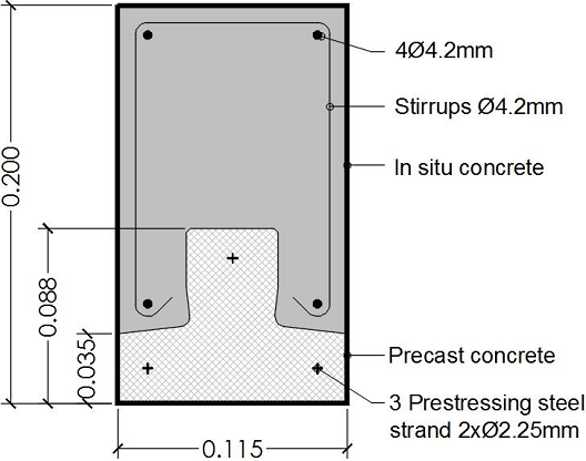
The characteristics of the materials composing the beams, in accordance with the regulation CIRSOC 201 (Centro de Investigación de los Reglamentos Nacionales de Seguridad para las Obras Civiles, 2005), are the following:
Regarding the prestressing force, it is not known exactly, although it was estimated. Because a common initial tensile stress of prestressing steel is around 1000 MPa, and since the total steel section is 23.86 mm2, the total prestressing force results in 23900 N approximately. This uncertainty is also often in structures in service, where the prestressing force of design is known, but the prestressed losses have been incurred during its lifetime up to the time of the study. It should be noted that not knowing precisely the value of the prestressing force, is not a limitation for the application of the methods of damage detection used here.
2.2 Test on Beam 01
The beam was placed in a simply supported way, with a distance between supports of 2.00 m and it was subjected to a punctual load in the center of the span. A total of 10 fleximeters, with an accuracy of 0.01 mm, were installed equidistant from each other, which allowed measuring the vertical displacements as the applied load increased.
The load was increased until it caused a discrete crack in the central area of the beam. In this instance, the depth reached by the crack and its maximum width in the lower zone of the beam was measured, as well as the precise position of the same. Then the beam was unloaded and it was observed, how, thanks to the action of prestressing, the crack was closed and the pre-load configuration was recovered almost totally. It should be mentioned that the increase in load was suspended when it was possible to observe a crack of significant magnitude with respect to the total height of the beam.
Next, the already damaged beam was again subject to load, measuring the vertical displacements at the same points. The information obtained was then used for the application of the damage detection methods.
Figure 2.a) shows the Beam 01 being tested. In the same, it is possible to see the load press, the load cell and the fleximeters installed on the beam. Since the structure that supports the beam can also suffer deformations, two of the fleximeters were installed in coincidence with the supports of the beam, in order to be able to correct the readings of the displacements obtained.
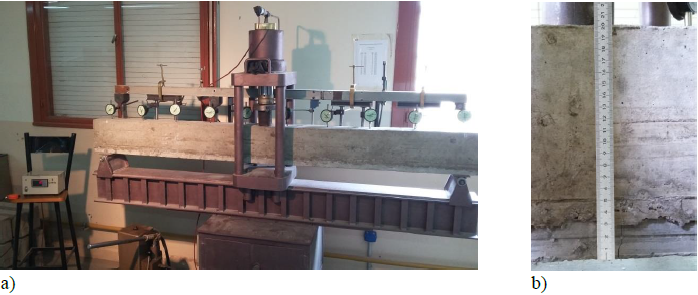
In Figure 2.b) the crack can be seen for the maximum load applied with the indication of the depth reached, which was 0.062 m (a/h = 0.31). It should be mentioned that when this depth of crack was reached, the increase in the load was suspended since the magnitude of the crack was significant enough. The maximum width of the crack was 0.35 mm and its position originated at x/L= 0.485.
Figure 3 shows the curves of vertical displacement vs. load applied, obtained for the two measurement points closest to the center, for the beam without previous damage (VSDP) and for the beam already cracked or with previous damage (VCDP).
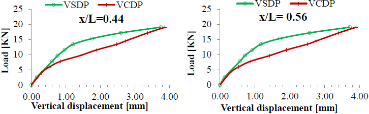
The symmetry of the displacements obtained can be noted since the crack originated very close to the center of the beam. For the loads applied on the beam without previous damage, a first zone of linear behavior and then a non-linear zone, which occurs from the beginning of the cracking, are observed. When the load was applied on the previously damaged beam, the curves of the displacements showed that they increased rapidly, but when the applied load approached the load that caused the crack, both displacement curves approached the same value. The latter indicates that the crack did not continue to spread.
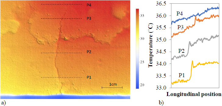
In addition, for detect discontinuities (cracks, different materials, etc.), on the Beam 01, another method of diagnosis of structural health was practiced, through the use of thermography (Tashan y Al-Mahaidi, 2014; Kabir, 2010; Abudayyeha et al., 2004). For the damage to be evident in a thermographic image, it is necessary to have a heat transfer in the studied element, in this case in the mass of the concrete. In a structure separating two different climatic conditions, this may be sufficient to note the greater heat transfer that occurs through the damaged zone (Pérez y Piedecausa, 2016). In the case of a beam under external environmental conditions, the thermal gradient could also exist, for example, due to exposure to the sun. In the studied beam, because it was at a uniform temperature inside the laboratory, it was necessary to apply a heat on its surface, which was done through an electric heating screen. The beam was then observed using a thermographic camera (Testo-890) and the images were captured and then processed using the software IRSoft 3.1 and Mathematica (Wolfram, 2015). It should be mentioned that the inspection was performed on the beam subjected to bending stresses, in order that the crack would be open with a maximum crack width of 0.30 mm. The results obtained for a maximum temperature difference of 17˚C between the concrete and the environment, are shown in Figure 4. It can clearly be seen the crack in the lower zone of the beam, and even thermal discontinuities in the zone of joining between the precast concrete and the "in situ" concrete. In addition, a sudden variation of temperature in coincidence with the crack is appreciated.
2.3 Test on Beam 02
The beam was simply supported, with a distance between supports of 2.00 m and was subjected to a punctual load in the center of the span. In the same way as for Beam 01, the vertical displacements were measured as the applied load increased. This load was limited so as not to cause damage on the beam. The beam was unloaded and then another point load was applied, in a position close to the right support. In this instance, the load increased until causing a discrete crack in that zone, of significant magnitude with respect to the total height of the beam. The depth reached by the crack was measured, as well as its precise position. Then the beam was unloaded and could be observed, how, thanks to the action of the prestressing, the crack was closed. Figure 5.a) shows the already generated crack. The depth of the crack resulted in a ratio a/h= 0.535, at the relative position x/L= 0.80.
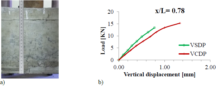
a) Measurement of the crack. b) Curves of displacements in the point x/L=0.78.
Figure 5 Test on Beam 02.
Next, the already damaged beam was again subjected to a centered load, measuring the vertical displacements at the same points as for the condition without damage. Figure 5b) shows the curves of vertical displacement vs. load applied, obtained for the point of measurement closest to the position of the crack, for the beam without previous damage (VSDP) and for the beam already cracked or with previous damage (VCDP).
It can be seen that the test performed on the beam without damage was kept within the zone of linear behavior, precisely in order to preserve the beam in such conditions. For this purpose, it was very useful to have the test information previously made on Beam 01.
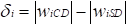
3. DISPLACEMENT VARIATION METHOD
This method consists of finding the vertical displacements in the damaged beam and comparing them with those of the healthy beam. This parameter can be considered as an index of the variation in the rigidity of the structure and is defined as:
 (1)
(1)
where w iCD is the vertical displacement of point i in the structure with damage and w iSD is the displacement of the same point in the structure without damage, both caused by the same increase in the applied loads. Graphing this difference of values in the vertical displacements, the presence of damage can be detected, observing the point at which the displacement variation is maximum.
It should be mentioned that, in order to apply this method, it is necessary to have the magnitudes of the displacements of the healthy beam (w iSD ), for the purpose of the comparison. This information can be available when inspections of the structure are made regularly or when the measurements can be made in other identical beams without damage.
The application of this method was carried out from the experimental displacements of the structure when going from a load condition "A" to a load condition "B" (Ercolani et al., 2015). In this case, the load condition "A" was considered, the corresponding to the point load of 7.79 KN and the load condition "B" for the point load of 9.67 KN.
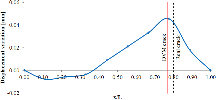
Figure 6 shows the graph obtained by applying this method for the Beam 01. It can be seen that the DVM can detect the presence of the damage and also locate it with good approximation. The real position of the crack in x/L= 0.485 is shown in the same graph, while the location x/L= 0.505 is obtained by applying the DVM.
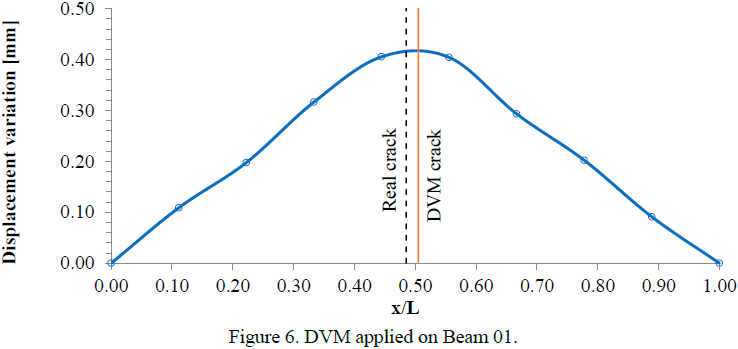
Figure 7 shows the graph obtained by applying the DVM on Beam 02. The same graph indicates the real position of the crack in x/L= 0.80, while the method gives the location of the damage in x/L= 0.77.
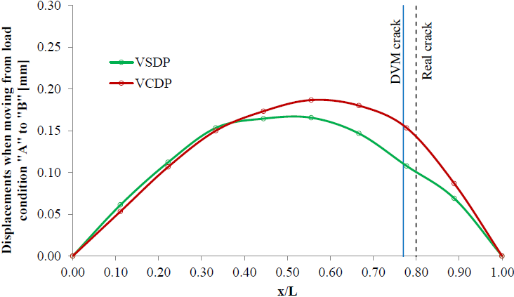
It can be seen in Figure 7, a zone in which the displacement variation is negative, although very close to being zero; that is to say, in that area, the displacements of the damaged beam, due to the increase of the load, were slightly smaller than those of the beam without damage. This may be due to the fact that the damage in the beam is so significant that the displacements suddenly increase in the area closest to the crack, whereas the area farthest to the crack suffers few alterations. To provide additional information, it is included Figure 8, in which the displacements caused by the increase of the load in the Beam 02 in both conditions, without previous damage (VSDP) and with previous damage (VCDP) can be seen. It can be observed that the maximum displacements increase towards the cracked zone, giving rise to the crossing of both curves of displacements.
It should be mentioned that the number of measuring points on the beams and therefore the distance between them, was conditioned to the equipment available for this purpose. In this case, the measuring points were spaced each L/9 and it may be noted to be a suitable separation for the experimental application of this method, although a higher density of measurements may allow an even more accurate location of the damage (Ercolani et al., 2015).
4. ELASTIC CURVATURE METHOD
The elastic curvature of a structure is given by:
 (2)
(2)
where w is the displacement of the structure, M is the bending moment, E is the modulus of elasticity of the material and I is the moment of inertia of the section. Then EI represents the flexural rigidity of the structure and it can be seen that if the structure has localized damage, that rigidity will decrease at the site of damage and therefore, the magnitude of the curvature at that location will increase. In addition, when greater is the magnitude of the damage, greater is the increase in curvature.
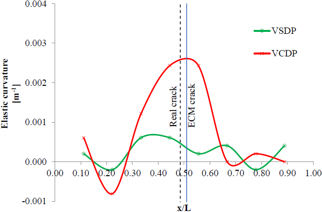
The calculation of the elastic curvature on the damaged structure can be carried out by measuring the displacements for a certain number of points of the structure and then, make an approximation by means of central finite differences, that is to say:
 (3)
(3)
in which s is the distance between two adjacent measurement points. In this way, the ECM consists in to measure the vertical displacements for a certain number of points of the structure and from them, obtain the curvature of the deformed structure, in order to detect anomalies in the same. Therefore, it can be noted that this method does not require knowing the displacement of the structure without damage, being this an important advantage with respect to the DVM, since it is frequently not available.
In the cases under study, the precision of the measurements, as well as the separation between the measuring points, are conditioned to the equipment available for this purpose, and may not be the most convenient for the application of this method. However, to compensate for this, the method was not only applied to the already damaged beam but also it was applied to the beam in conditions without damage, in order to be able to compare the results in both conditions.
In the same way as for the DVM, the application of the ECM was carried out from the displacements obtained in the structure, when going from a load condition "A" (point load of 7.79 KN) to a load condition "B" (point load of 9.67 KN).
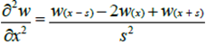
Figure 9 presents the application of the ECM for the Beam 01, for the conditions without damage and with damage. It can be seen that the ECM allowed to identify the presence of the damage in the Beam 01 and to approximate its location. The method gives the position of the damage in x/L= 0.51, which results in an absolute error of 2.5%, compared to the true location of the crack in x/L= 0.485.
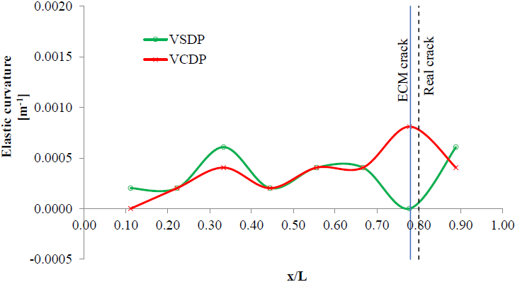
On the other hand, Figure 10 shows the application of the ECM for the Beam 02 in the conditions without damage and with damage. In this figure, it can be noticed that the ECM allowed to identify the presence of the damage in the Beam 02 and to have a good approximation of its location. The method gives the position of the damage in x/L = 0.78, which results in an absolute error of 2% with respect to the true location of the crack in x/L = 0.80.
5. CONCLUSIONS
In this work was experimentally evaluated the potentiality of two damage detection methods based on static responses, applied to two prestressed concrete beams constructed in the laboratory. These methods are the displacement variation method and the elastic curvature method. In addition, infrared thermography was successfully applied to one of the beams for visualization of the damage. From the analysis of the results obtained, it can be concluded the following:
• The application of the two methods is simple in its implementation. In addition, they can be used together, if the necessary data are available, which allows a better diagnosis.
• As is to be expected, the prestressing force, tend to close the crack, so it makes the manifestation of damage, in both methods, less noticeable than in the case of reinforced concrete beams. However, this manifestation was sufficient to show the existence of damage, by the methods, for both the beam with a crack in the central zone and the beam with a crack in the vicinity of one of the supports.
• Regarding the determination of the damage position, the differences between the real position of the crack and the location indicated by the DVM were 2.0% and 3.0% for the beams 01 and 02, respectively. On the other hand, with the ECM, differences of 2.5% and 2.0% were obtained for these beams. These errors are within a range more than acceptable for an experimental work.
• It was demonstrated that the thermographic images processing can be a valuable tool for the detection of cracks or anomalies, as well as alterations in the homogeneity of the material.
6. ACKNOWLEDGMENTS
The authors thank the Engineering Department and the General Secretariat of Science and Technology of the Universidad Nacional del Sur (UNS), the Consejo Nacional de Investigaciones Científicas y Técnicas (CONICET) and the Comisión de Investigaciones Científicas de la Prov. de Buenos Aires (CIC), for the support provided for the development of these investigations.
REFERENCES
Abudayyeha O., Al Batainehb M., Abdel-Qaderc I. (2004), An imaging data model for concrete bridge inspection. Advances in Engineering Software 35, pp. 473-480. [ Links ]
Bertolini L., Elsener B., Pedeferri P., Redaelli E., Polder R. B. (2014), Corrosion of Steel in Concrete: Prevention, Diagnosis, Repair, 2nd Edition, Wiley-VCH, p. 434. [ Links ]
Centro de Investigación de los Reglamentos Nacionales de Seguridad para las Obras Civiles, (2005), CIRSOC 201 Reglamento Argentino de Estructuras de Hormigón, INTI. [ Links ]
Dai L., Wang L., Zhang J., Zhang. H. (2016), A global model for corrosion-induced cracking in prestressed concrete structures, Engineering Failure Analysis 62, pp. 263-275. [ Links ]
Dawari V. B., Vesmawala G. R. (2013), Modal curvature and modal flexibility methods for honeycomb damage identification in reinforced concrete beams, Procedia Engineering 51, pp. 119-124. [ Links ]
Domínguez P. N., Orbanich C. J., Ortega N. F. (2007), Localización de fallas en vigas de fundación de hormigón armado, Mecánica Computacional 26, pp. 1373-1386. [ Links ]
Ercolani G. D., Ortega N. F. , Felix D. H. (2015), Detección de fisuras en vigas de hormigón pretensado, RADI - Revista Argentina de Ingeniería 6, PP. 90-97. [ Links ]
Kabir S. (2010), Imaging-based detection of AAR induced map-crack damage in concrete structure, NDT and E International 43, pp. 461-469. [ Links ]
Karayannis C. G., Chalioris C. E. (2013), Design of partially prestressed concrete beams based on the cracking control provisions, Engineering Structures 48, pp. 402-416. [ Links ]
Lu Q., Ren G., Zhao Y. (2002), Multiple damage location with flexibility curvature and relative frequency change for beam structure, Journal of Sound and Vibration 253 (5), pp. 1101-1114. [ Links ]
Orbanich C. J. , Robles S. I., Ortega N. F. (2009), Detección de Fallas en Plateas de Fundación Elástica, Mecánica Computacional 28, pp. 1897-1917. [ Links ]
Pandey A. K., Biswas M., Samman M. M. (1991), Damage detection from changes in curvature mode shapes, Journal of Sound and Vibration 145, pp. 312-332. [ Links ]
Pérez Sanchez J. C., Piedecausa García B. (2016), Termografía infrarroja aplicada en cúpulas históricas: identificación y análisis de sistemas constructivos. Informes de la Construcción 68, pp. 1-9. [ Links ]
Robles S. I. , Ortega N. F. , Orbanich C. J. (2011), Damage evaluation in shells from changes in its static parameters, The Open Construction and Building Technology Journal 5, pp. 182-189. [ Links ]
Tashan J., Al-Mahaidi R. (2014), Detection of cracks in concrete strengthened with CFRP systems using infra-red thermography, Composites: Part B 64, pp. 116-125. [ Links ]
Tong T., Liu Z., Zhang J. , Yu Q. (2016), Long-term performance of prestressed concrete bridges under the intertwined effects of concrete damage, static creep and traffic-induced cyclic creep, Engineering Structures 127, pp. 510-524. [ Links ]
Wolfram S. (2015), An Elementary Introduction to the Wolfram Language. Wolfram Media, Inc. [ Links ]
Received: August 03, 2017; Accepted: September 06, 2017
 Este es un artículo publicado en acceso abierto bajo una licencia Creative Commons
