


 nova página do texto(beta)
 Inglês (pdf)
 Artigo em XML
 Referências do artigo
 Enviar este artigo por email
 Citado por SciELO
  Similares em
SciELO
Similares em
SciELO 
 Permalink
INTRODUCTION
Measuring the volume of solids, liquids, or gases is essential for commerce, health, environmental care, or science (Mandal et al., 2019; Lorefice, 2009). The usual way to measure the volume of a liquid is through an instrument that contains it, which could be made of several materials and have different shapes (Lorefice, 2009; Gupta, 2006). The typical shape of a volumetric instrument is the cylindrical shape at the reading scale zone, like in pipettes, burettes, one-mark volumetric flasks, graduated cylinders, or beakers. Regarding the manufacturing material, glass is the most established for laboratory volumetric instruments (Zumdahl, Zumdahl, and Hall, 2014; Belgacem and Cherif, 2023).
The calibration of volumetric instruments can be carried out by one of three methods: geometric, volumetric, or gravimetric. Geometric methods are used for large volumes, whereas volumetric and gravimetric methods are used for the glassware, i.e., one-mark or graduated-scale glass instruments with capacities below one liter (Gupta, 2006). However, the gravimetric method is the accredited laboratories’ primary method because it is the most accurate (Liang et al., 2013; Boineau, Plimmer, and Mahé, 2020). Also, the coverage range of its application goes from a couple of liters to microliters (Liang et al., 2013; ISO 20461, 2000; Batista, Almeida, and Filipe, 2009), which corresponds to many of the most used volumetric instrument’s capacities.
The uncertainty during liquid volume measurement with the gravimetric method has several influence quantities, like the water and air densities, the mass pieces density, temperature, etc. However, it has been well established that the higher experimental contribution to the volume determination uncertainty comes from the meniscus reading (EURAMET CG-19, 2018; ISO 4787, 2010; ASTM E542-01, 2012; Win, 2021). The meniscus reading depends on the technical skills of the operator in locating the lowest point of the (usually) concave meniscus, and on the internal diameter of the volumetric instrument at each graduation line of interest (EURAMET CG-19, 2018; ISO 4787, 2010).
Several international standards for cylindrical-shaped glassware provide internal diameter specifications (ISO 648, 2008; ISO 385, 2005; ISO 835, 2007; ISO 1042, 1998). Also, there is a procedure to calculate the meniscus reading uncertainty for the graduated scale and the one-mark volumetric apparatus (EURAMET CG-19, 2018). Optical methods for volume measurement in cylindrical-shaped glassware have also been reported, (Liu, Bamberg, and Bamberg, 2011).
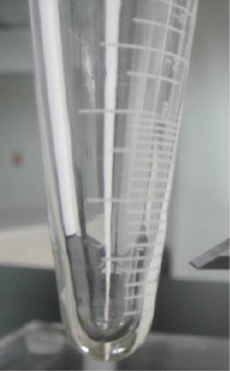
On the other hand, there are several conical glass instruments (CGI), such as Imhoff cones (DIN 12672, 2001), centrifuge tubes (ASTM D1796-11, 2011), or water traps (ASTM D95-13, 2018), that have graduation lines marked on a conical section instead of a cylindrical one. These instruments are widely used in several fields, like (bio) fuels (Aisyah et al., 2019), oil (Ortiz, Quintero, and Arévalo, 2016), or soil analysis (Arturi, Seijas, and Bianchi, 2019), and it is worth studying them (Biazon, Jesus, and de Oliveira, 2015) because they are also economically relevant (Burgess, 2022).
CGI needs to be verified or calibrated like other measurement instruments, as requested for some international standards (ISO 9001, 2015; ISO 14001, 2015). However, for CGI, the meniscus reading uncertainty determination is not a one-stop calculation. The internal diameter is variable along their reading section, so they are not one-diameter graduated scale apparatuses or one-mark ones.
Even among the several types of CGI, differences related to internal diameter measurement methods arise due to their full-body shape. An Imhoff cone allows the measurement of its wall thickness with a vernier caliper only at the top. Still, proceeding that way is impossible for a centrifuge tube due to its mouth being constricted in shape for closure with a stopper (ASTM D179611, 2011). Additionally, the lack of standardized international specifications and variations due to manufacturing processes could cause different internal diameters at the same nominal volume in CGI of the same type.
Recently, the use of an optical comparator for the internal diameter measurements in CGI has been reported (Purata et al., 2021). However, an optical comparator is an expensive and complex instrument with high fixed and variable costs and a no-short training time. Also, using a vernier caliper to measure the CGI’s wall thickness and subtract it twice from the outer diameters is not always feasible, as exemplified above, or advisable if the wall thickness varies along the body of the CGI.
An alternative that does not need direct measurements of the internal diameter of the CGI is shown in this work. Assuming that the internal diameters of the CGI are perfect circles, they were modeled as part of a series of aligned truncated cones. Then, the inner diameter values were calculated with height gage measurements at the graduation lines of interest, provided a constraint of perfect alignment was met. Six height measurements were made for every graduation line that met the constraint, returning to the zero-height reference after each measurement. The measurements were carried out sequentially, from the bottom to the top of the CGI. Finally, a power regression model with good fit and prediction properties was used as an alternative for the lines that did not meet the restriction.
The results were compared against the direct measurements of internal diameters when using an optical comparator, as reported elsewhere (Purata et al., 2021). The absolute values of the relative error concerning an optical comparator direct measurement averaged less than ten percent for the CGI studied. Therefore, the proposed approach solves the situation where no optical comparator is available, nor a vernier caliper can be used for internal diameter measurements of the CGI.
This paper is organized as follows: the literature revision, problem statement and objectives are covered in this introduction. Next, the geometry of the conical instruments is considered to propose their modeling approach. The experimental section details both the hardware and the procedures to obtain the experimental data and the uncertainty budgets. The results and discussion section follows, showing the measurement and internal diameter determination values and the regression results. Finally, the conclusions of the research are declared.
Objectives
To introduce an alternative method for assessing the internal diameter of the CGI without requiring direct measurements.
To propose an approach that overcomes the limitation of unavailable or unaffordable optical comparators, or useless vernier calipers (unable to measure close-to-the-tip wall thickness) for internal diameter measurements in CGI.
GEOMETRIC CONSIDERATIONS
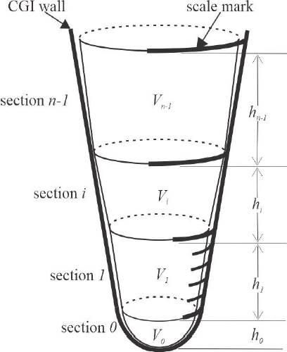
The rationale behind the approach proposed in this work is schematically shown in Figures 1 and 2. The body volume of a CGI in Figure 1 is modeled as a series of n truncated cones in Figure 2, each delimited by two graduation marks adjacent or separated by one or more intermediate marks. The deviations of perfect circularity of the CGI body at every graduation mark are assumed negligible. As a restriction of the modeling approach, starting from the tip of the CGI towards its top (’mouth’), the lower base of any cone frustum must be smaller than its upper base.
Source: Courtesy of CIATEC, A.C.
Figure 1 Geometric profile of a conical glassware instrument. Note the unevenness of the wall thickness.
Source: Author´s own elaboration.
Figure 2 The proposed modeling approach for the conical glassware volume segmentation.
At the tip of the CGI, the series of truncated cones are attached to a semi-ellipsoid of revolution, the section 0 in Figure 2, which models the blunt tip of the instrument, from the very first graduation mark to the bottom of the container. A straight taper exhibits a very pointed end and does not come close to the actual geometry of the CGI tip (see Figure 1). A paraboloid of revolution still shows a sharp tip (additional pictures are available in (Burgess, 2022) and (Purata et al., 2021). A hemisphere constrains the height of section 0, h0, always to equal its radius, which is invalid. And finally, the most stringent constraint of a spherical cap requires h0 always to be less than its radius, so it does not apply either. Therefore, the semi-ellipsoid of revolution is chosen because it allows room for different height-radius ratios, which could cover various CGI tips.
The volume formula for the semi-ellipsoid of revolution, section 0 of Figure 2, is as follows (Beer et al., 2018):
where V0 is the nominal volume, D0 is the internal diameter, and h0 is the height of the semi-ellipsoid section, all of them always referred to at the very first graduation line of the CGI.
For the subsequent truncated cone sections (section 1 to section n − 1 of Figure 2), the following equation applies:
Subject to
where Vi is the volume, hi is the height, Di−1 is the lower internal diameter, and Di is the upper internal diameter of section i of the CGI (i ≠ 0). The restriction guarantees that the major base of a cone frustum is the minor base of the next one in the tip-mouth direction, as shown in Figure 2.
Internal diameter calculation method
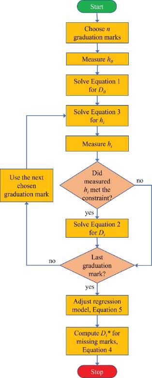
The proposed height gage procedure for the calculation of the internal diameter values of a CGI follows:
Choose n graduation marks where you need to know the internal diameter values of the CGI, e.g., calibration or verification points. Always include the lowest scale mark of the CGI, and prefer long graduation lines (like the upper ones of section i and section n − 1 in Figure 2) while avoiding selecting the short contiguous lines (like inner marks of section 1 in Figure 2). This last recommendation is critical in zones where the spacing between marks decreases to almost equal their thickness.
There will be n − 1 different truncated cone sections plus one semi-ellipsoid section in the CGI. Number the sections in ascending order; the first section from the bottom of the CGI as section 0, the next one as section 1, and so on until the top of the CGI as section n − 1.
Let each section’s corresponding known nominal volumes to be V0 to Vn−1, from the bottom to the top of the CGI.
Measure the height of the semi-ellipsoid section 0, h0, and then solve Equation 1 for D0, the first internal diameter value from the bottom of the CGI.
Solve the constraint in Equation 3 for hi (for i = 1, . . . , n−1), and then measure (see the Experimental procedure below) the actual height of the corresponding cone frustum hi.
If the restriction is not met, repeat step 5 with the following graduation mark of the selected ones in step 1. If the constraint is satisfied, solve Equation 2 for Di: the next internal diameter value of the CGI.
If there are other internal diameters to compute, return to step 5 for the following graduation line selected; otherwise, finish the procedure.
In steps 4) and 6) above, a negative root arises when solving the quadratic equations in Di, which is physically meaningless for a diameter value and must be discarded.
Internal diameter data curve fitting (when the geometrical constraint was not met)
The restriction in Equation 3, imposed by the geometrical approach, could avoid calculating the internal diameter for a particular graduation mark, provided it is smaller than its predecessor in the bottom-up direction of the CGI. One way to overcome this situation is to fit a curve to the values of the internal diameter that did meet the constraint.
The computed internal diameter data obtained through this height gage method are not as accurate as a direct inner diameter measurement. Therefore, fitting a curve that passes precisely through each data is unnecessary, as in interpolation techniques. Instead, the trend of the set of calculated internal diameters must be represented, and the least-squares regression is a better option (Chapra and Canale, 2021).
The relationship between a nominal volume and the correspondent internal diameter in a CGI could follow a simple power equation (Purata et al., 2018):
where a and b are the constants of the power regression model. Once all the valid internal diameter values have been calculated through Equation 1 and Equation 2, parameters a and b could be determined through logarithmic linearization of Equation 4:
Thus, a least-squares linear regression of the log transformed known data (log Di, log Vi) enables obtaining a and b to be used in Equation 4 (Chapra and Canale, 2021). Then, it will be possible to get the estimated internal diameters, Di *, for the graduation lines that had not met the constraint in Equation 2 for any given value of Vi. The whole geometric approach steps are illustrated in Figure 3.
Source: Author´s own elaboration.
Figure 3 Flowchart for the indirect determination of internal diameters.
It is worth noting that the constraint given in Equation 2 appears here as a geometric equation since the geometrical approach of the suggested height gage method. However, it has a more profound impact on the numerical accuracy of the technique because it embodies the assumption that all the nominal volumes, V0 to Vn−1, are exact.
EXPERIMENTAL PHASE
For the CGI height measurements, a digital height gage was used. The digital height gage had an absolute linear encoder, so there was no risk of over-speed error during the measurements. Also, the height gage had a resolution of 0.01 mm and a range of (0 to 600) mm. All the height measurements were done with the height gage over a granite surface plate to ensure the reference plane was flat (see Figure 4).
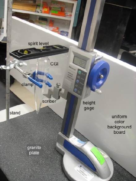
Source: Courtesy of CIATEC, A.C. Labels by the author.
Figure 4 The proposed modeling approach for the conical glassware volume segmentation.
On the other hand, the CGI studied were a centrifuge tube and an Imhoff cone, with nominal capacities of 100 ml and 1 L, respectively. Both CGI are made of borosilicate glass 3.3, and has a graduation line thickness of 0.4 mm.
Experimental procedure
The procedure to make the height measurements is as follows:
Ensure the verticality of the CGI with the stand arrangement most suited for the particular CGI. For a centrifuge tube, tweezers and a stand could be enough (Fig. 4), while for an Imhoff cone, a special stand designed to hold Imhoff cones vertically could be needed (see Purata et al., 2021).
Using a spirit level, make sure the CGI is leveled (Figure 4).
Set the lowest internal point of the CGI as zero height reference in the height gage.
Take the height reading at the graduation mark of interest. The first one must always be the lowest scale mark of the CGI. This work did six measurements for every height value, returning to the zero-height reference after each measurement.
Repeat step 4 for each graduation mark for which you want to know its internal diameter. Once measurements have started, keep leveled (step 2) and do not move the CGI until all desired measurements have been made.
The height value of each section of the CGI, h0 to hn−1 as depicted in Figure 2, could be obtained by differences in the average height readings taken in step 4.
The proper setting and keeping of the zero-height reference (step 3) are critical. A piece of fabric could be used to immobilize an Imhoff cone in its stand, or a centrifuge tube must be secured with tight clamps. Moreover, leveling must be tested with the spirit level in several directions. Also, do not touch the CGI, bracket, or granite base plate during measurements; touch the height gauge only in the parts provided, according to your training and the user manual. Finally, a good practice is to put a uniform color as a background to enhance the adjusting process of the graduation line and the scriber.
Height measurement uncertainty budget
The ISO/IEC 17025 standard establishes that laboratories must identify contributions to measurement uncertainty, as well as that when the test method does not allow a rigorous evaluation of uncertainty, an estimate must be made based on the understanding of theoretical principles or heuristics of the method (ISO/IEC 17025, 2017). The uncertainty analysis of the height measurements is shown in Table 1. A list of uncertainty sources is included (Salsbury, 2022; ISO 13225, 2012), complementing the standard uncertainty value and the expanded uncertainty with a coverage factor k = 2. Even when all familiar uncertainty sources were considered, only repeatability, standard (calibration), and resolution were significant contributors, with 51 %, 36 %, and 13 % of participation, respectively.
Table 1 Expanded uncertainty analysis of the height measurements
| No. | Source | Standard uncertainty / mm |
|---|---|---|
| 1 | Repeatability | 2.25E-02 |
| 2 | Calibration of the height gage | 1.60E-02 |
| 3 | Resolution | 5.77E-03 |
| 4 | Standard and measurand temperature difference | 2.80E-05 |
| 5 | Thermal expansion coefficient | 1.42E-06 |
| 6 | Environmental and measurand temperature difference | 1.85E-06 |
| 7 | Standard and measurand thermal expansion coefficient difference | 1.88E-05 |
| Combined standard uncertainty | 0.028 | |
| Expanded uncertainty (k = 2) | 0.056 |
Source: Author´s own elaboration.
As mentioned before, the most significant contribution to the uncertainty of the diameter estimation by the height gage measurement is due to the deviation of the actual CGI shape from the mathematical model. And it is not only for the modeling of the CGI tip as a semi-ellipsoid (Equation 1) but also for the assumption implicit in Equation 2 that the complete CGI conical section has a constant conicity which cannot be achieved since the thickness of the walls of the conical section increases towards the tip of the cone.
RESULTS AND DISCUSSION
Following the experimental procedure outlined above, the heights of two CGI, a centrifuge tube, and a glass Imhoff cone were measured at several graduation marks. The centrifuge tube is an example where a Vernier caliper could not measure the several external diameter values and then discount twice the wall thickness measured with the Vernier caliper. An Imhoff cone was also studied to extend the scope of the study toward CGI with higher nominal capacity values. Also, for most Imhoff cones, most common Vernier calipers do not have jaws of adequate length to make direct measurements of the internal diameter.
Table 2 shows 12 height measurement results for the centrifuge tube, whereas Table 3 shows the nine height measurement results of the Imhoff cone. In each case, the results are the average of six height measurements. It is worth saying that the centrifuge tube measured here (one of the most common types) has a cylindrical section above the conical section (ASTM D1796-11, 2011). That is why the maximum capacity of the centrifuge tube mentioned in the experimental section is not covered.
Table 2 Internal diameter values through height measurements for a centrifuge tube using the proposed method
| Nominal volume / mL | Measured height / mm | Computed internal diameter / mm |
|---|---|---|
| 0.05 | 4.835 | 4.444 |
| 0.25 | 12.108 | 7.276 |
| 0.5 | 17.087 | 8.695 |
| 0.75 | 20.483 | 10.634 |
| 1 | 23.273 | 10.729 |
| 1.5 | 27.577 | 13.543 |
| 3 | 36.703 | 15.370 |
| 4 | 41.170 | 18.353 |
| 6 | 48.412 | 19.148 |
| 8 | 54.128 | 23.004 |
| 10 | 58.807 | 23.655 |
| 20 | 76.442 | 29.961 |
Source: Author´s own elaboration.
Table 3 Internal diameter values through height measurements for an Imhoff cone using the proposed method.
| Nominal volume / mL | Measured height / mm | Computed internal diameter / mm |
|---|---|---|
| 0.1 | 4.273 | 6.685 |
| 1 | 18.378 | 11.156 |
| 3 | 36.447 | 12.573 |
| 5 | 46.693 | 18.753 |
| 10 | 64.403 | 19.166 |
| 20 | 86.517 | 28.520 |
| 40 | 114.508 | 31.774 |
| 100 | 163.482 | 46.744 |
| 1 000 | 382.025 | 95.336 |
Source: Author´s own elaboration.
In both Tables 2 and 3, the internal diameters were calculated following the procedure described in the section "internal diameter calculation method," as well as the flow diagram in Figure 3. Special care must be taken with the conversion factors of measurement units, which are not explicitly included in the procedure. Furthermore, it is recommended that when solving Equation 2 for Di, it is done using the general formula for quadratic equations, first determining the required coefficients and the independent term.
In both Table 2 and Table 3, the value of the computed internal diameter increases as height measurement does, and this is possible only if the constraint in Equation 2 is satisfied for each pair of graduation lines selected one after the other.
Assessment of the height gage approach
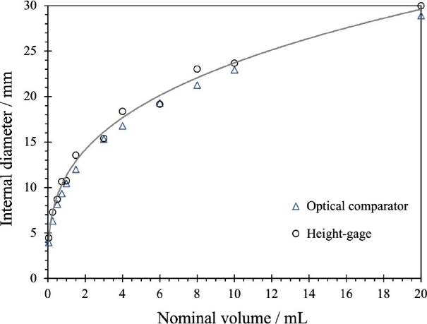
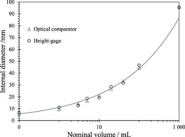
Verifying the proposed height gage method is essential to evaluate its performance and potential use as an alternative for internal diameter direct measurements. Direct measurements with an optical comparator (Purata et al., 2021) were used as reference values to assess the proposed height gage method. Figure 5 and Figure 6 exhibit the computed internal diameter values resulting from height measurement versus the direct measurements obtained with an optical comparator for both CGI.
Source: .Author´s own elaboration.
Figure 5 Diameter direct measurement with optical comparator versus the height-gage method proposed here, and its adjusted power equation: D*i = 11.33Vi0.3204. Centrifuge tube case.
Source: Author´s own elaboration.
Figure 6 Diameter direct measurement with optical comparator versus the height-gage method proposed here, and its adjusted power equation: D*i = 11.195Vi0.2966. Imhoff cone case.
As seen in Figure 5, internal diameter values for the centrifuge tube calculated with the height gage approach tend to be above the direct measurement made with the optical comparator. The same behavior is observed in Figure 6 for the Imhoff cone case, but here at least three of the nine measurements had lower values with the height gage method than those direct measurements taken with the optical comparator. Note that in Figure 6 the X-axis scale is logarithmic. Also, the expanded uncertainty achieved with the direct measurement is ten times lower (Purata et al., 2021) than the proposed one (see Table 1). That is why no ’error bars’ are shown in Figures 5 and 6.
The maximum relative error of the height gage approach compared to a direct internal diameter measurement using an optical comparator was 15 % for the centrifuge tube, with an average error of 7.5 % for the 12 inner diameters computed. Whereas for the Imhoff cone, the maximum relative error was 19 % with a 9.8 % average relative error.
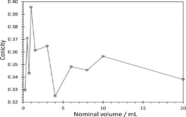
Another visible behavior of the results is that the inner diameter value from the proposed method approaches and moves away from the obtained with direct measurement alternately. This is due to changes in the actual conicity of the CGI. For example, Figure 7 shows a graph of the conicity for the studied centrifuge tube. Here, the conicity was calculated using the measured values of internal diameter with the optical comparator and the height of each truncated cone section (Figure 2). The alternation between higher and lower values of the real conicity of the centrifuge tube is then reflected in the similarity between the actual value of the internal diameter and the value predicted by the proposed geometric model. A similar result was obtained for the Imhoff cone case.
Internal diameter data power regression (when the geometrical constraint was not met)
Figures 5 and 6 include a power equation in their caption, relating the nominal volume as the independent variable to the inner diameter approximation as the dependent variable. Table 4 shows the results of the power regression model for the CGI analyzed obtained with the R language for statistical computing (R Core Team, 2023).
Table 4 Statistics results summary from the power regression models of both CGI studied.
| Element | Centrifuge tube | Imhoff cone |
|---|---|---|
| Coefficient, a | 11.330 | 11.195 |
| Power, b | 0.320 4 | 0.296 6 |
| Degrees of freedom | 10 | 7 |
| Residual standard error | 0.040 | 0.126 |
| p-value | 6.909E-13 | 4.441E-07 |
| R-squared | 0.995 | 0.978 |
Source: Author´s own elaboration.
For the centrifuge tube, the p-value was 6.9E-13, whereas for the Imhoff cone was 4.4E-07. Hence, the regression model is significant in both cases. Additionally, the R-squared is close to one in both cases, so the model correctly explains the data provided trend.
The power regression model only aims to make it possible to deal with the graduation lines where the constraint imposed by Equation 2 does not allow the computation of an internal diameter value. So instead of using Equation 2 on these graduation marks, Equation 3 could be used. Table 5 has two additional predicted inner diameter measurements versus the directly measured ones for both CGI analyzed in this work. These two nominal values initially did not meet the restriction in each CGI, even though they have long graduation lines, so they were discarded when executing the procedure illustrated in Figure 3.
Table 5 Comparison between measured and adjusted internal diameters of the CGI studied.
| CGI | Nominal volume / mL | Measured diameter / mm | Fitted diameter / mm |
|---|---|---|---|
| Centrifuge tube | 2 | 13.281 | 14.147 |
| 5 | 18.181 | 18.975 | |
| Imhoff cone | 2 | 12.266 | 13.750 |
| 2.5 | 13.305 | 14.691 |
Source: Author´s own elaboration.
As shown in Table 5, the average of the relative error is very close to the obtained with the computed figure for both CGI: 6.5 % and 4.4 %, for the nominal volumes of 2 ml and 5 ml, respectively, for the centrifuge tube and the Imhoff cone, at nominal volumes of 2 ml and 2.5 ml, relative errors of 12.1 % and 10.4 % were obtained. Then, a power regression model fits well the calculated data and can be used to get any internal diameter not calculated with Equation 2, provided it is included inside the interval of original nominal volume values for which the height was measured.
For both CGI studied, whose height was measured and whose internal diameters calculation with Equation 2 met its constraint, the sum of the relative errors of the first half of the graduation marks doubles the respective sum for the second half of the graduation lines. That means that errors are considerably higher at low volume nominal values, and it is due to the wall thickness unevenness, which decreases towards the top of a CGI. Also, the deviation contribution of the geometric approximation of Equation 1 contributes to a more considerable error just at the starting point.
Finally, it is worth saying that an optical comparator is a piece of equipment that is much more complex and expensive than a height gage. Also, the time spent getting results is another critical factor to consider in judging the convenience of the proposed height gage method.
CONCLUSION
A new method to determine the internal diameters of CGI indirectly is proposed. The relevance of the results arises from the critical contribution to the uncertainty of the meniscus reading, which depends on the diameter, during the gravimetric calibration of volumetric instruments. The technique uses a height gauge to measure the height of a tick mark and avoids using an optical comparator, which is more expensive and complex. Furthermore, the method is especially suitable for cases where it is impossible to measure the wall thickness of the glassware to subtract it twice from the external diameter value at a given graduation line, as in the case of centrifuge tubes. The absolute values of the relative error versus direct optical comparator measurements averaged ten percent for a pair of CGIs studied, a centrifuge tube, and an Imhoff cone. This work could be extended to other types of CGI, such as water traps, or even to conical volumetric instruments of another material, such as those made of plastic (ISO 384, 2015), which probably have a more uniform conicity given their manufacturing process.
The usefulness of the proposed method lies in its possible use when other alternatives are not an option, either because the equipment is not available (an optical comparator) or because the instrument is not suitable for the task (a vernier caliper used in a centrifuge tube). Although the uncertainty achieved with the method cannot be better than that obtained with a vernier caliper, the technique is more versatile because fewer measurements are required per graduation line (measuring height versus measuring external diameter and wall thickness) and, therefore, less handling of fragile instruments. However, an extension of the present investigation is required in which the proposed method is contrasted against the use of other methods for determining the internal diameter of CGI. This is part of future works related to this research.

