


 nueva página del texto (beta)
 Inglés (pdf)
 Artículo en XML
 Referencias del artículo
 Enviar artículo por email
 Citado por SciELO
  Similares en
SciELO
Similares en
SciELO 
 Permalink
Introduction
Current energy needs are mostly being met by fossil fuels, which are easily obtained, stored, and transported because of the large investments made to create, build, and maintain the system. Despite all advantages fossil fuels have provided for our society, they also had negative effects on the environment, including air, water, and soil pollution. In addition, a significant drawback of management and combustion of fossil fuels is the emission of greenhouse gases (CO2; CH4; etc.) and their accumulation in the atmosphere. [1] Moreover, there is a finite supply of fossil fuels that will inevitably force the transition to other energy sources, in particular the combination of the various renewable energy technologies. [2] Solar energy conversion to electricity or useful heat, and clean fuels technology have been growing and developing to the point where these technologies are very accessible today due to their low cost, efficiency, and reliability. Electrochemistry has proven to be an invaluable tool in the technological development of solar energy conversion systems. [3]
In this context, researchers at several Mexican institutions that were recently awarded the emeritus status at the highest level of the “Sistema Nacional de Investigadores” have made significant contributions, which we would like to highlight and place in context in this work.
The contributions are numerous, for example, on the investigation of electrochemical solutions that are used in the technological development of solar energy conversion systems. We can highlight the work on the effect of polyethoxylated additives on the reduction mechanism in zinc electrodeposition by Yunny Meas, [4] the study of electrochemical nucleation mechanism of cobalt by Ignacio González, [5] and electrochemistry of transition metal complexes as a function of a pH by Jorge Ibáñez. [6] These studies illustrate the advantages of electrodeposition technology for the synthesis of materials for energy applications over vapor phase deposition techniques.
Some of the electrodeposition advantages that we can highlight are: easy control over growth conditions by controlling the potential or the current density applied during the process. It also offers good control of the area to be covered, can be implemented easily for coverage of larger areas with short synthesis times, and it is comparatively cheap compared to other deposition techniques such as sputtering, PVD, etc.
The electrodeposition process has a wide range of applications in many fields of emerging technologies, such as fabrication of meta-materials, [7] the synthesis of metals within porous alumina, applications in nano-batteries, [8] fabrication of mesoporous and nanostructured layers of semiconductor oxides for applications in dye-sensitized solar cells, [9, 4] deposition of wiring in microelectronics, [10] the synthesis of semiconductor oxides for applications in resistive random access memories, [11] and synthesis of selective coatings for solar thermal applications, [12,13] among others.
Electrodeposition is a robust technology and is particularly attractive to provide efficient large-scale solar energy conversion systems. Electrodeposition can produce films with a wide range of morphologies, which can significantly improve the performance of the systems in which they are applied, as shown by the Yunny Meas group in their work on the electrodeposition of pure zinc (Zn) and alloy Zn with another metal such as Co, Ni, Fe and Mn onto a steel surface.[12,13] The group has focused to the improvement of the electrodeposited films using acidic or alkaline electrolyte solutions, showing that the pH can promote the formation and deposition of different oxide compounds, which generate compact and stable passivation layers. [14-17] They also showed that the use of different electrolyte solutions with or without organic additives can improve the electrodeposition of ZnO onto carbonaceous, metal and semiconductor substrates. [4,12]
The objective of this section is to provide a review of the solutions used for the electrodeposition of films applied to solar energy conversion systems.
Thermal energy systems
Solar absorptance and thermal emittance
Fig. 1 illustrates the expected spectral behavior for an ideal selective coating. The ideal selective coating should reflect the least amount of incident radiation in the range of 300 - 2500 nm, while in the range of 2500-15000 nm the reflectance should be as high as possible, in order achieve a very low thermal emittance. In short, the real selective coating would have high absorption in the solar range and low thermal emittance in the infrared range.
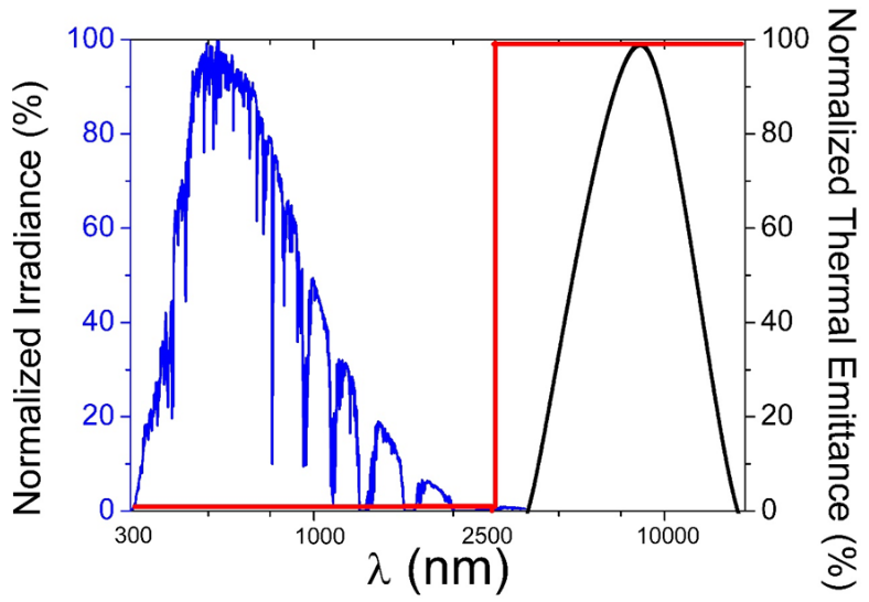
Fig. 1 The red line represents the ideal reflectance curve for a selective coating, with low R / high Abs in the solar spectrum range, and high R / low Emit. in the infrared range. The blue line represents the normalized solar spectrum AM 1.5, the black line represents the normalized black body thermal emittance at 100 °C.
The solar absorptance and thermal emittance are calculated according to the equations 1 and 2, as reported by several groups. [18, 19] The solar absorptance can be determined by weighting the reflection spectrum against the solar radiation spectrum ASTM G173-0329, using equation 1.
where R(λ) is the wavelength dependent reflectance, and the black body radiation as a function of wavelength and temperature is given by
Cermet materials
Solar collectors are a type of heat exchanger whose purpose is to take advantage of solar energy and convert it into thermal energy (heat), generally associated with the increase in temperature of a fluid (air, water, oil, etc.) that circulates through the collector. Solar energy can be used to generate domestic hot water at 60 ºC or thermal fluids to 400 ºC to generate electricity, for example. [20] A selective coating is a material that is applied to the surface of an element that is part of a solar collector to reduce thermal radiation losses. The good performance of a selective coating depends to a great extent on the optical properties of the material. One of the materials used as selective coating are the so-called cermets, which are ceramic-metal composites. Cermet materials have suitable characteristics for solar thermal applications, as they are composed of metallic clusters embedded in dielectric matrix and are characterized by a high absorption of the solar spectrum and excellent reflective properties in the infrared, which means that Cermet materials should have high solar absorptance (α) to increase the temperature and low thermal emittance (ε) to control the rate at which the generated heat is directed towards the desired heat-accepting material. Cermet materials can be obtained by various techniques such as sputtering, [21,22] anodization, [23] and electrodeposition. The most important electrodeposited cermet materials for thermosolar applications are the so-called “black metals”, i.e. black nickel, black cobalt and black chromium; however, there are many more promising systems that have not yet been tested in solar collectors. [24] Depending on the electrodeposition solution composition, the properties of the cermets can be controlled and may have very different characteristics such as high stability to environmental conditions or temperature. The “black metals” are widely used in industry due to their efficient conversion of solar radiation into thermal energy.
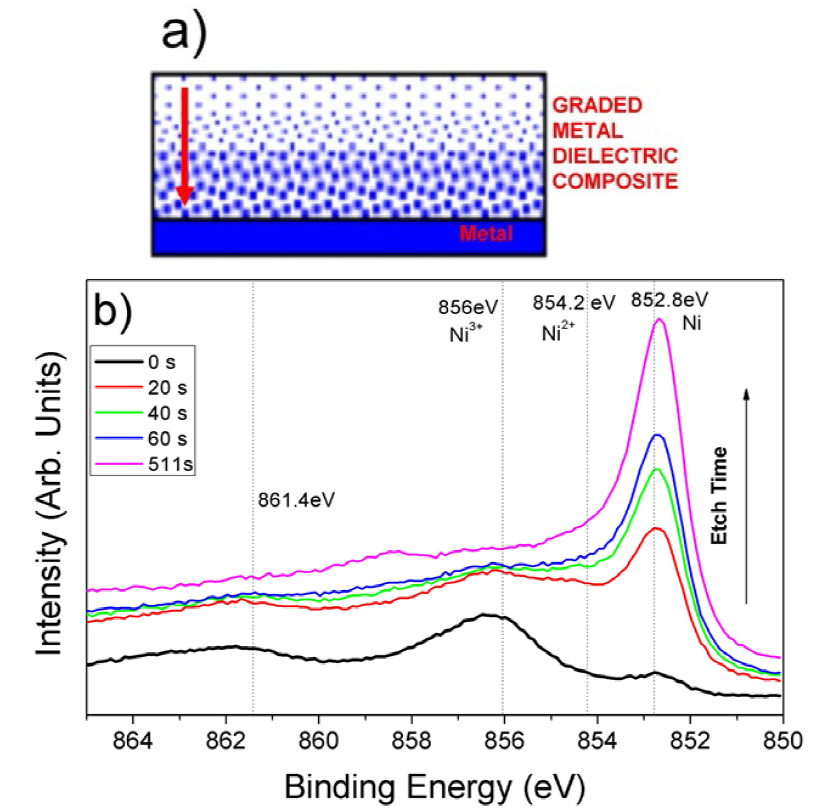
Fig. 2(a) shows a schematic representation of a cermet material where the graded refractive index was achieved by changing the metal composition from the base to the surface of the absorber coating. Fig. 2(b) illustrates the characterization of a black nickel cermet material using the XPS depth profile analysis. At t = 0, the XPS spectrum is dominated by surface oxides, while upon erosion using sputtering, the metal content in the film increases as illustrated by the peak at 852.8 eV for metallic nickel (Ni0). Related with the graded metallic content in the film, the electrodeposited black nickel shows a graded refractive index.
Black nickel
Black nickel is widely used material in thermosolar applications; depending on the synthesis solution the material properties can be adequately under harsh weather conditions. There are at least 3 different solutions to obtain black nickel, which are summarized in Table 1.
Even though the mechanisms for the formation of black nickel are complex and depend on various factors such as surface pH and temperature, it is accepted that in the case of solution 1 three electrochemical reactions take place simultaneously. The reactions referred to are labeled as solutions 1, 2 and 3 in Table 1. The black nickel electrodeposition process involves the cogeneration of Ni metal and Ni(OH)2 in the metallic substrate. [28] Additionally, there is electrolysis of water that generates OH¯ groups, which cause an increase of the local surface pH and oxidize Ni(OH)2 generating NiOOH, which are the two species coexisting on the surface of black nickel. [29] Hence, the formation of black nickel occurs according to the following Faradaic and chemical reactions:
In solution 2, the presence of SCN¯ induces the formation of zinc and nickel sulfide compounds in the films obtained. These sulfur compounds, however, cause a low resistance to humidity of the black nickel coatings. The low number of precursors in solution 1 is the main advantage over other solutions, which simplifies the maintenance process. The high concentration of chloride helps to dissolve the counter electrode, which typically consist of nickel. The soluble counter electrode helps to maintain an adequate composition of the solution and to have homogeneity of the covered area.
Black cobalt
An important contribution of the group of Prof. Yunny Meas in this field is the study of cobalt-based baths and electrochemical processes for corrosion protection applications, such as Zn-Co films on steel substrates. It has been shown that the use of organic compounds such as benzylideneacetone as an additive in the electrodeposition solution induces homogeneous Co deposition onto a steel substrate due to an increase of the limiting current density of cobalt deposition without modifying the overpotential and at the same time inhibit the formation of zinc hydroxides on the substrate, [14,15] Cobalt-based baths were used in the synthesis of solar absorber films for solar collectors, [13,15,30-36] hydrogen evolution reaction in mechanically alloyed Co30Ni70 powders, [37] and electrochemical nucleation and growth processes of cobalt on glassy carbon electrodes (GCE). [38-40]
Black cobalt is a material with good optical properties and good thermal stability. There are various solutions for the electrodeposition of black cobalt. Nucleation studies show the associated mechanisms to obtain cobalt metallic films even at basic pH. [41] The metallic films are subsequently thermally oxidized to obtain a kind of black cobalt. Depending on the composition of the solution, compounds such as sulfides, oxides, hydroxides or oxyhydroxides can be formed, giving different properties to the coatings of this material. Table 2 shows the main solutions used for the synthesis of black cobalt.
Black cobalt deposit occurs according to the following Faradaic and chemical reaction. For the solution 1.
For solution 2 the electrochemical reactions are the reduction of metallic cobalt, which is aided by H3BO3 for the control of the local pH. Subsequently, the metallic cobalt is thermally oxidized, giving films with good solar absorptance.
One of the important contributions of Prof. Ignacio González and collaborators in this field is the analysis of the kinetic parameters of cobalt electrodeposition on a glassy carbon electrode (GCE) using transient measurements. Prior to their work, it had not been possible to establish the conditions to differentiate the study of the nucleation mechanisms and the growth of cobalt crystals, accompanied by simultaneous hydrogen evolution in aqueous chloride solutions. They found that, under specific experimental conditions in about 10 mM CoCl2 in 1 M NH4Cl (pH = 4.66), from -1.18 at -1.28 V vs. SCE the deposition of cobalt is preceded “by a progressive nucleation where the superposition of the diffusion zones plays a very important role in the first stages of the formation of nuclei”. Their study allowed, for the first time, to determine the density number of the nuclei formed, the nucleation rate of the stationary states, the kinetic parameters and finally, the mechanism of the cobalt deposition process. [5]
For solution 3 the mechanism is complex, the accepted Faradaic and chemical reactions for the black cobalt electrodeposition are:
The electrochemical reduction of the complex CoSCN + promotes the formation of OH¯ y SCN¯ groups. When this bath is used the thermal stability of cobalt black is found to be quite good. The heat treatment promotes the formation of Co4O3, CoO and sulfur desorption.[30] Solution 4 was only investigated on small-area substrates and was not evaluated on complete full-size collectors.
Black chrome
Despite the drawbacks related to the toxicity of chromium VI, electrodeposited black chromium is one of the most used selective coatings. Electrodeposited coatings are reported to have high solar absorptance and low thermal emittance. A disadvantage of black chromium plating solutions is the high current density used in the deposition of the films. [46,47] Non-aqueous electrodeposition solutions have recently been reported which use chromium III salts to avoid the toxicity, [42, 48] however, the optical properties achieved are not as good as those reported for chromium VI. Table 3 summarizes the main solutions used for the electrodeposition of black chrome.
Metal oxides
Selective coatings based on metal oxides have recently gained attention due to the need to develop systems of high solar absorptance and low emittance that can be stable at high temperatures exposed while to air [53] and can be obtained with an easily scaled-up synthesis method such as electrodeposition. Unlike cermets, these systems do not have metal in their composition, which makes it possible to apply them at temperatures of more than 300 °C. Related to the latter, a field of application of these materials is in solar collectors that use solar concentration such as parabolic trough solar collectors. [22] Solar absorption is increased by morphology and surface roughness of the films. The high thermal and chemical stability are related to the spinel type structure that they adopt. [54] Table 4 summarizes the metal oxide selective coatings systems with high solar absorptance and low thermal emittance.
Table 4 Main metal oxide solar absorbers coatings.
| System | Optical Properties | Synthesis Method | Applied to collector prototypes | References |
|---|---|---|---|---|
| Cu-Cr-Mn- Oxide | α = 0.92, ε = 0.65 | Precipitation | No | [53] |
| Co-Oxide-Iron- Oxide | α = 0.94, ε = 0.20 | Spray pyrolysis | No | [55] |
| CuO | α = 0.92, ε = 0.55 | Spray pyrolysis | Yes | [56,57] |
| Co3O4 | α = 0.90, ε = 0.2 | Thermally treated substrate | Yes | [58] |
| Manganese-iron oxide | α = 0.93, ε = 0.52 | Spray coating | Yes | [59] |
| Co3O4 | α = 0.93, ε = 0.09 | Spray Pyrolysis | No | [60] |
| Co-Mn-Oxide | α = 0.90, ε = 0.15 | Electrodeposition | Yes | [54] |
In Table 4 it can be seen that only a few electrodeposited coatings have been applied to planar or tubular collectors prototypes, indicating a window of opportunity to further develop electrodeposition technology for these materials.
A common method for the electrodeposition of oxide-based selective coatings takes advantage of the NO3¯ reduction reaction, which is represented in reactions 10 and 11, where M2+ is a metal cation. In the case of nitrate reduction, the Nernst potential of metal ions does not determine the process, but rather the solubility product of hydroxides that allows the simultaneous deposition of metal oxides that could have very different reduction potentials without first depositing the metal. [54]
Flat plate collector
Thermosolar systems can be classified into non-concentrating and concentrating types. In the non-concentrating systems, there are flat plate collectors and evacuated tubes. In the concentrating type (T≥120 °C), central tower receiver parabolic trough, Fresnel-type concentrator, and parabolic dish systems are located. The flat plate collector systems with electrodeposited selective coating are used for low-temperature applications (T<120 °C) . Currently, there are many reports in flat plate collectors using sputtered selective coatings and paints, [61] however, there are few reports that can be cited where solar absorber coatings were synthesized by electrodeposition to the size of a prototype and then characterized their performance. Recent improvements to these systems involve the use of thermochromic coatings, [62] nanomaterials in the heat transfer fluid, [63] and implementation of complete collector vacuum. [64]
The efficiency of flat plate collectors is obtained from the absorbed power Q A for the plate, termal losses Q 1 , the solar irradiance G T , and the aperture area A of the collector:
The ratio QA/AGT It is related to maximum conversion efficiency ƞ0, while Q1/A is proportional to the total heat transfer coefficient U 1 (W/m2K) and the average temperature difference Δ T between the heat transfer fluid in the upper heat pipe of the collector and the ambient temperature. The dimensionless factor F is introduced, which considers the resistance of the heat flow between the absorber and the heat transfer fluid. The maximum collector efficiency ƞ 0 is equal to the product ατ with α the solar absorptance of the selective coating and τ the transmittance of the collector cover.
Fig. 3 shows a diagram of the main components of a flat plate solar collector. For clarity, the flow tubes are shown ahead of the absorber plate. Table 5 shows a summary of the prototype solar collectors efficiencies built with selective electrodeposited coatings. It can be noted that in the case of flat plates there are no reports for black cobalt. Black cobalt has mainly been investigated in vacuum-evacuated collectors and planar have only recently been reported.[30]
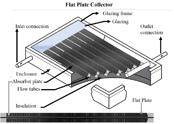
Table 5 Summary of the efficiencies of prototype solar collectors built with selective electrodeposited coatings.
From Table 5 it can be seen that the most efficient prototypes are those built with black chrome; however, they are the most expensive systems to obtain since high current densities are used in the synthesis, and the solution used is more difficult to maintain. Black cobalt salts are more expensive compared to black nickel; however black nickel shows the lowest efficiency. Thus, a balance must be achieved for the desired properties of the selective coating between durability and costs, such that the cost of the investment is covered during the useful life of the solar collector.
ZnO dye sensitized solar cells for solar energy conversion
In this section we will analyze the electrochemical aspects of synthesis and characterization of films for energy applications through the process of converting sunlight to electrical energy. We will focus on ZnO dye-sensitized solar cells (DSSCs) since in its construction and operation there are several electrochemical processes that can be reviewed, and which highlight the contributions of scientists in Mexico.
DSSCs are a fascinating photoelectrochemical system used to harvest solar light, and the system is still at the forefront of research and development even after thirty years of the first reports. This was clearly demonstrated in 2022 when a power conversion efficiency of 15.2 % under standard AM-1.5G simulated sunlight with a long stability of 500 h was reported, related to the implementation of a to preadsorbed hydroxamic acid derivative monolayer on the surface of TiO2. [66]
The functioning principle of DSSCs involves four basic steps: i) Light absorption, where photons are absorbed by the photosensitizer electrons are promoted to the excited state; ii) the promoted electrons are injected into the conduction band of a semiconductor oxide; iii) electrons are transported through the nanostructured, mesoporous semiconductor to reach the back contact where they are collected in the external circuit and travel at the counter electrode; iv) at the counter electrode, electrons reduce the tri-iodide to iodide, thus providing the electrons to re-generate the oxidized dye. A schematic representation of these processes is shown in Fig. 4(a). The working electrode (WE) scaffold needs to be a nanostructured and mesoporous metal oxides with high surface area, and the dye with needs to have good affinity to the metal oxide surface and have a high light harvesting efficiency.
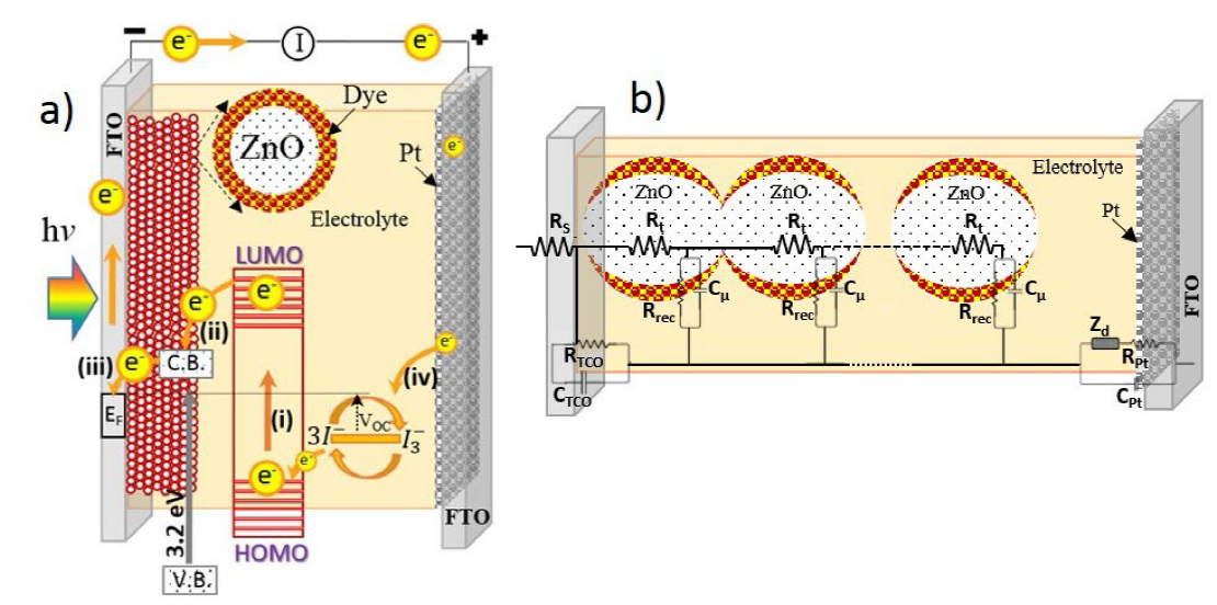
Fig. 4 (a) Schematic representation of the electronic processes in DSSCs, (b) Electrochemical impedance spectroscopy (EIS) circuit used on a DSSC where each circuit element provides information about charge transfer.
Traditionally, nanostructured, mesoporous TiO2 is used as WE for efficient DSSCs, however, ZnO is an interesting alternative as an n-type material with direct electronic transitions with a band gap of 3.2 eV, and a higher bulk electron mobility (200 cm2 V -1 s-1) which is about 2 orders of magnitude higher than that for TiO2. Among the known techniques are those where semiconductor materials such as TiO2 and ZnO are first manufactured using some of the growth techniques such as sol-gel and then a paste is prepared to later fix the films on the substrates, the best known are: doctor blade deposition,, screen-printing, inkjet-printing, spin-coating, dip-coating, etc. [67-71] Another alternative for the manufacture of an electrode are the deposition techniques, where the semiconductor is synthesized and at the same time the film is fixed on the substrate, the most common are: electrodeposition, [17,72,73] plasma-enhanced chemical vapor deposition, hydrothermal deposition, [74,75] among others. [76-78] Electrodeposition is an attractive technique due to its high deposition speed, good control over thickness and morphology of the film, as well as low temperature deposition conditions. [79,80] It is worth highlighting the contribution made in this field by the work group of Yunny Meas, who provided valuable analyses on the electrodeposition of metals from ionic liquids and solutions with organic additives, which can later be thermally oxidized to form the required metal oxide. [16,4,81]
ZnO electrodeposition as photoanode in DSSC
In this section we will discuss aspects related to the electrodeposition technique of ZnO films, which were used as electrodes for DSSCs applications. There are several routes for the synthesis of ZnO by electrodeposition. [2, 7, 14, 15, 65, 72, 74, 77-79] The first one is through the reduction of nitrate represented in reactions 10 and 11. Reactions 14 and 15 show the mechanism accepted to obtain ZnO from NO3¯ reduction.
It is reported that the reduction rate constant for nitrate is small, so this reaction is the rate determining step in the ZnO synthesis process.[82] Another strategy used to obtain ZnO is by reducing water in a nitrate bath; the film obtained is thermally treated to produce the crystalline oxide. Using this strategy, polymers can be co-deposited, which upon removal by the heat treatment results in a porous film.[9] This latter strategy is useful when 10 μm ZnO thick, porous films are desired. For a solution composed by Zn(NO3)2 at low temperature (≤ 50 oC), it is necessary to apply a cathodic potential more negative than -0.96 V vs Ag/AgCl to generate the reduction of nitrate ions and induce the formation of Zn(OH)2 on the substrate and subsequent transformation to ZnO. The deposition leads to direct formation of crystalline thin films under near-room temperatures; this feature is important for flexible solar cell applications using ITO-PET foil substrates.[83] The film morphology plays a key role, since the transport of the electrons, once they are injected into the ZnO, and the available surface area are important factors required for high efficiency solar cells. An intrinsic advantage of the electrodeposition process is that the morphology and surface area of ZnO can be adjusted through the solution composition or current density applied.[84]
Hence, the ZnO film morphology fabricated by electrodeposition from nitrate solution can be adjusted according to the experimental requirements. Table 6 shows a summary of different DSSCs with ZnO electrodeposited as photoanode, without and with additives in the synthesis solution. One can observe the significant effect of the morphology on the efficiency of the cell, as well as the relationship between the applied potential and the obtained morphologies from a nitrate bath. In addition, the morphology dependence on the precursor salt and bath additives is highlighted.
Table 6 Summary of different solution additives for ZnO electrodeposition and the resulting film morphology (Morph.).
| Solution | Potential or current density (V vs Ag/AgCl) | Solution synthesis additive | Morph. | Dye | Eff. (%) | Ref. |
|---|---|---|---|---|---|---|
| Zn(NO3)2 | -1.4 | Non | Nanosheets | N719 | 0.031 | [85] |
| -1.1 | Non | Nano-rods | N719 | 2.09 | [86] | |
| -1.1 | Non | Hexagona particles l | N3 | 0.13 | [87] | |
| -1.045 | Non | Nano-rods | N3 | 0.59 | [88] | |
| Hexamethylenetetramine | Nanowires | N719 | 1.02 | [89] | ||
| -1.2 | PEG 3400 | Nano-flakes | N719 | 1.8 | [9] | |
| -1.2 | SDS | Lamellar structures | N719 | 1.9 | [90] | |
| -0.95 | Sodium acetate and sodium citrate | Nanofibrous networks | N719 | 3.78 | [91] | |
| -1.1 | Sodium acetate trihydrate | Nanosheets | D149 | 4.65 | [92] | |
| -1.1 | PVP40 | Nanosheets | MG- 207 | 1.05 | [93] | |
| 0.05 M Zn(NO3)2 | -0.3 mA/cm2 | Non | Nanowire | N719 | 0.32 | [84] |
| 0.3 M Zn(NO3)2 | -0.3 mA/cm2 | Non | Nanosheets | N719 | 0.02 |
In nitrate solutions with lower metal salt concentration slower growth kinetics takes place, which facilitates layer-by-layer growth of hexagonal plates to form a nanorods morphology; [84] the decrease of concentration results in the preferential growth of a plain with respect to others. On the other hand, a variation of the potential applied may generate the formation of different ZnO morphologies, including nanosheets. The use of polyethoxylated compounds as additives in the electrolyte solutions influences the growth and structure of the deposits. Surfactants such as sodium dodecyl sulfate (SDS) can also be used as an additive during electrodeposition to work as morphology modulator. [85,86]
The difference in morphology is expected to affect the recombination process, in particular, the electron transfers from ZnO to the oxidized dye and the redox couple. For example, the recombination rate is reduced when electrons are injected into the nanowire ZnO morphology; when compared to the ZnO nanosheet, the trapping of electrons at ZnO grain boundaries reduces resulting in faster electron extraction. The cell efficiency was increased 10 times for the nanowires with respect to the nanoflakes; however, the cell efficiency was not the highest.[86] Other factors such as the type of dye should also be considered. In the case of ruthenium-based dyes, it is reported that the acidity of the carboxylic acid functional groups of the molecule can dissolve ZnO by forming complexes with Zn 2+ . [73,88] To avoid this problem during the sensitization process, organic dyes such as D-149 that bond via a cyanoacrylic moiety have been developed. This effect of the dye is very relevant and from the reports found in the literature, the cells sensitized with D-149 are characterized by the highest efficiency reported for ZnO.
The second route for ZnO electrodeposition consists of the use of chlorides in the solutions, which involves the electroreduction of oxygen to hydroxide ions. The process is represented by reaction 17. In the presence of ZnCl2, the OH¯ ions generated at the electrode are consumed in precipitation of ZnO represented by reaction 18.
This electrodeposition route can produce highly transparent and very well adherent hybrid thin films that can also sustain a high dye loading. It has also been shown that the addition of the organic dye Eosin Y to the ZnCl2 electrodeposition solution accelerates the reduction of O2, thus improving the film growth and, as a consequence, increases the dye absorption. [94] Table 7 shows the most relevant works that use this route to obtain ZnO. This route is currently being applied at prototype fabrication level for the fabrication of porous ZnO films on glass and plastic foil substrates.
As seen in the table, the best efficiencies are obtained with the D149 dye for this synthesis route. D149 is an indoline-based dye, which is a high extinction coefficient and metal-free organic sensitizer, which promises to lower the manufacturing costs of DSSCs.
Characterization of ZnO DSSCs by Electrochemical Impedance Spectroscopy
Electrochemical impedance spectroscopy (EIS) is a characterization technique interpreted in terms of an associated electrical circuit model. The transmission line model developed for the DSSC is shown schematically in Fig.4(b). [97-100]
The EIS spectra exhibited the typical shape for a DSSC under small Fermi-level perturbations, and can consist of up to three arcs: one for the impedance at the counter electrode (Cpt; Rpt), generally observed at high frequencies; one at low frequencies related to ionic transport in the electrolyte solution (Zd); and a semicircle at intermediate frequencies attributed to the time constant consisting of the resistance for charge transfer between semiconductor and electrolyte, i.e. recombination (Rrec), and the chemical capacitance (Cµ). RS is the series resistances, the RTCO and CTCO are the resistances and capacitance of the transparent conductor oxide, respectively, the Rpt and Cpt are the resistances and capacitance of the platinum nanoparticles. Even in an EIS impedance spectrum depending on the electron transport dynamics, a transport resistance may deform this medium frequency arc. Fitting the experimental spectra to this transmission line model provides data for the recombination resistance and the capacitance as a function of applied bias. [101-104]
As an example, Fig. 5 shows a set of typical EIS spectra for a DSSC based on a mesoporous, nanostructured ZnO film as a function of light intensity and, hence, open circuit potential. The behavior of the Nyquist curves illustrates that the semicircle at high frequencies is practically the same for all voltages, while the second semicircle decreases as the voltage increases, which is the part associated with the ZnO film according to the transmission model (Fig. 4(b)). The analysis in terms of the above described model allows to determine the recombination resistance vs. open circuit voltage, which is generally found to exhibit an exponential dependence according to:
where kB is the Boltzmann constant, T the absolute temperature and
where 𝛼 is an adimensional parameter that describes the average energy of an exponential distribution of trap states below the semiconductor conduction band. [99, 101-103] The average lifetime of the electron is (𝜏𝑛) can be obtained using the next equation:
The lifetime is significant parameter, since it allows us to understand the recombination kinetics in balance with charge transport and extraction The next step is to compare the average diffusion length, which can be obtained from the lifetime taking into account the electronic diffusion coefficient, with the film thickness:
Where 𝐿𝑛 represent the diffusion length of the electron, L is the film thickness, and 𝑅𝑇 is the charge transport resistance, [105-107] if this ratio is ≤ 1, this means that the photogenerated electron will not reach the FTO contact, but recombines with the electrolyte; if this ratio is larger than 1, the photogenerated electron can be collected in the external circuit giving a good performance of a DSSC. Hence, the optimal thickness of the film depends on the transport and recombination kinetics, indicating that good control is needed over all these parameters. [88,91,107-109]
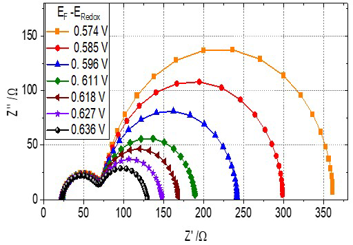
Fig. 5 Impedance spectra in the Nyquist representation (imaginary vs. real part of the impedance) for a DSSC fabricated using a mesoporous, nanostructured ZnO. The ZnO nanomaterial was synthesized by sol-gel chemistry methods and the film deposited by the doctor blade technique. The measurements were performed at open circuit potential indicated in the legend, which was varied by changing the incident light intensity.
Reviewing the following reports, we show the additional relevance of the use of EIS for the characterization of the electrochemical cells. EIS was used to characterize ZnO cells with different morphologies obtained by electrodeposition and sol-gel coating, finding that the number of traps present at the grain boundaries are lowest in electrodeposited cells. It was explained by the observation that charge diffusion is faster in large crystallized nanoporous grains, which are typically obtained by electrodeposition of ZnO. The chemical capacitance was lowest for these cells. [110] With the help of EIS it was determined that the morphology and film texture were the dominating factors that determine the solar ZnO cell performance. [11] On the other hand Prof. Ignacio González using EIS detect the presence of surface states related to grain boundaries at the core shell ZnO/TiO2 interface. These resulted in a modification of the transport of charge carriers changing the photocatalytic activity of the material for the photodegradation of 4-chlorophenol in aqueous solution. [70]
ZnO DSSCs with hybrid technology
Our group is working on another strategy to improve dye adsorption; a simple method is to increase the surface area of ZnO using a two -step ZnO deposition method: first, a relatively thin film is deposited using doctor blade deposition and second, a thin, roughening film is applied using electrodeposition of ZnO on top of this.
For this purpose, ZnO nanoparticles were prepared using forced hydrolysis from zinc acetate and NaOH in ethanol. The ZnO nanoparticle radius could be tuned in the range from 6 nm to 18 nm by addition of a controlled amount of water. A colloidal suspension of 20 wt.% ZnO was prepared by mixing ZnO powder with water and ethanol (30:70) while stirring at room temperature. [112] Next nanostructured, mesoporous ZnO films were prepared on transparent conducting oxide (FTO) by doctor blade deposition. After deposition of films these were sintered at 450 °C in air inside a furnace to get a mesoporous film. Fig. 6 shows the SEM images of three films sintered; each film has nanoparticles of different radius as determined by XRD: for the H1 sample the radius is 5 nm; for H2, 12 nm; and for H3, 8 nm, respectively.
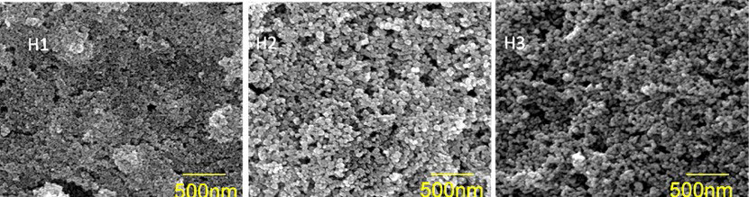
Fig. 6 SEM images of mesoporous ZnO films obtained by forced hydrolysis employing the doctor blade deposition. The radius for the nanoparticles in H1 is 5 nm, for H2 this is 12 nm, and for H3 the average radius is 8 nm (as determined from XRD using the Scherrer equation).
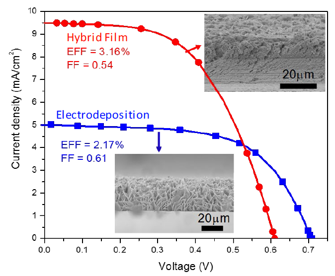
After sintering the films, the substrates were submitted to an electrodeposition step using a zinc nitrate bath (hybrid films). Although there are several aspects that affect the efficiency of a cell, we will narrow the discussion down by analyzing the efficiency of the DSSC through the I-V curve shown in Fig.7 the short-circuit current can associated with the amount of surface area and dye adsorbed if we assume that under these conditions recombination is negligible. In this figure we can see that the hybrid film (red line with circles) has a higher current density of 9.5 mA/cm2, while the cell prepared with only an electrodeposited ZnO film (blue line with squares) has a higher voltage of 0.7 V. The reason for this behavior is that electrodeposited particles go through the ZnO mesoporous films and deposit on the FTO surface free space. This/2 reduces the contact of
Conclusions
In this review, we highlight the contributions of Mexican scientists to the development of the fundamental electrochemistry and to the implementation of electrochemical processing and characterization in material sciences. We illustrate these contributions with examples of the use of electrochemistry in a variety of solar energy conversion systems. We show that the electrochemical route is a technique with great potential to be applied in the synthesis and deposition of materials for sunlight harvesting. Using electrodeposition, we can obtain excellent film quality with good solar absorption properties, including cermets and semiconductor oxides. This technique provides the possibility to control the film morphology by management of specific additives, changing the applied potential, or changing the metal precursor.
Currently, electrodeposition is applied for the scale-up and fabrication of thermosolar systems for low and medium temperature applications, either through the synthesis of cermets or metal oxides. In the development of the sections, it was argued that for low temperature systems (flat-plate solar collectors) cermet-type materials are mainly used and for medium-high temperature metal oxides promise high solar absorptance, low thermal emittance and high durability related to the spinel-like crystalline structure.
In addition, we highlight the electrochemical aspects of the dye -sensitized solar cell, which can be fabricated using electrodeposition of mesoporous, nanostructured ZnO film, as well as the versatility of electrochemical impedance technique as a powerful tool to characterize electrical processes in solar cells. In the section ZnO DSSCs with hybrid technology, it was demonstrated that the electrodeposition technique can be used to take advantage of untapped opportunities by other deposition techniques, notwithstanding the results can be optimized by other groups using new deposition techniques, or better electrodeposition processes.

