1. Introduction
Aluminum oxide (Al2O3) is the second hardest ceramic that exists, only after diamond. The atomic structure of the ceramic materials is responsible for their great chemical stability against aggressive chemical agents that cause corrosion. Alumina exists in many metastable polymorphs and depending on the temperature with which the process is carried out, its optical properties changes. For example, from 300 °C to 700 °C, the alumina coatings are opaque (Kobayashi, Ishizaka, & Kurokawa, 2005; Levin & Brandon, 1998; Lux, Colombier, Altena, & Stjernberg, 1986).
Alumina in the form of coatings is a material of technological interest for multiple applications in optical, electronic components, as well as a material that is resistant to oxidation at high temperatures (Blittersdorf, Bahlawane, Kohse-Höinghaus, Atakan, & Müller, 2003). The corrosion and thermal oxidation protection of structural steels and composite polymeric materials for aeronautical or automotive applications requires the development of thin alumina films to act as an oxidation barrier for applications with temperature ranges from 200 ° C to 600 ° C (Lazar et al., 2014).
There exist physical and chemical deposition techniques for manufacturing films and coatings of different nanostructured materials. Among the chemical processes, one of the most used is the chemical vapor deposition (CVD) (Martin, 2010; Ohring, 2002). In this technique a chemical reaction of a mixture of gases or chemical vapors is carried out to obtain a solid product in form of thin film or coating deposited on substrate. Currently, variants of the technique are being developed and improved. For example, direct liquid injection metal organic chemical vapor deposition (DLI-MOCVD), allows the formation of epitaxial crystalline layers at low temperature (Serrano, Serrano, Juárez, & Juárez, 2016). With the automatic control of this technique is possible to achieve a constant vapor flow into the heating chamber, which favors the homogeneous growth rate of the layers (Mun et al., 2016; Serrano, Martínez, Juárez, Serrano, & Juárez, 2017). AISI 1018 steel is widely used in industry, although it is commonly protected to increment its time-life. The present research shows the advantage of using an electromechanical injector in the vaporization chamber and allows the precursor to transform into amorphous Al2O3 in order to produce a layer of this material on the AISI 1018 steel substrate. The flow of atomized solution is controlled by an electromechanical injector which controls consumption the precursor provided in vapor phase to the chamber.
2. Experimental
2.1. Operation parameters and materials
The coating deposition was carried out by DLI-MOCVD, at 40 psi, horizontal, hot wall CVD reactor, using aluminum tri-sec-butoxide as precursor. The deposition was carried out at 370 °C, with argon as the carrier gas. The details of the deposition process are shown in Table 1.
Table 1 Operation parameters of the DLI-MOCVD experiment.
| Substrate | AISI 1018 steel |
| Vaporization chamber temperature | 180 °C |
| Deposition temperature | 370 °C |
| Carrier gas | Argon |
| Gas flow | 200 cm3 |
| Pressure | 40 psi |
| Deposition time | 80-90 min |
| CVD precursor | Aluminum tri-sec-butoxide |
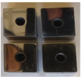
In the present research commercial low carbon steel AISI 1018 (Fe 99.06%, C 0.17%, Mn 0.7%) was used as the substrate material (1/2 pulg. squared solid profile) used in rods, tensors, steering bolts and chains (Figure 1). Due to its ductility it is ideal for cold transformation processes: stamping and folding. The specimens were cut with dimensions of 12.5 mm x 12.5 mm and 13 mm thick. The surface was polished by using different abrasive papers: 240, 400, 600, 800, 1000 and 2000. Subsequently diamond paste of 5 μm, 3μm and 1μm was used for obtaining mirror finish surface. A scanning electron microscope (Quanta 3D FEG) equipped with energy dispersive spectroscopy (EDS) technique was used to determine the chemical composition of the substrate. The composition of the low carbon steel AISI 1018 is given in Table 2.
Before deposition, the substrates were cleaned using acetone and an ultrasonic bath during 20 min.
2.2. Precursor and Solvent
The alumina precursor (2 g) was dissolved in cyclohexane (80 ml) to form a final concentration of 0.02 M. Cyclohexane was selected as a solvent since there are studies where it has been observed that it favors the growth of spherical structures with few agglomerations (Gunby, Krumdieck, Murthy, Masters, & Miya, 2015).
2.3. Deposition
The mixture of the precursor with the solvent was introduced in the vaporization chamber using the direct liquid injection technique (DLI) with a pressure of 40 psi, time of 900 s and 1 Hz. With these parameters it was possible to inject 8 ml of solution at a constant flow of 0.010 ml/s.
Once the solution has become vapor, it was introduced into the reaction chamber at a temperature of 370 °C.
3. Results and discussion
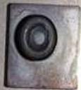
With the experiment and the parameters mentioned above, was possible to obtain a well quality Al2O3. The range of deposition temperatures reported for amorphous films was between 250 °C and 550 °C (Pradhana, Reucroft, & Ko, 2004). Also (Maruyama & Arai, 1992) reported that amorphous films may contain or not (OH) groups depending on deposition conditions. The advantage of using direct liquid injection is that it´s possible to obtain homogenous dark blue films as seen in the Figure 2.
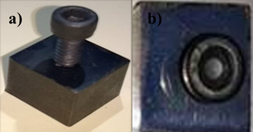
Figure 2 Al2O3 layer deposited on the AISI 1018 steel by the DLI-MOCVD technique, a) isometric view, b) top view.
To carry out the characterization of Al2O3 layer, the substrate layer was removed as recommended by the ASTM C1624 (Figure 3) (ASTM C1624 - 05, 2015). According to the norm, the Chisel Test is commonly used for testing relatively strong and thick coatings (thicker than 0.005”/0.125 mm), so, the test was made penetrating through into the interface between the coating and substrate. In this case a sharp cold chisel penetrates the layer
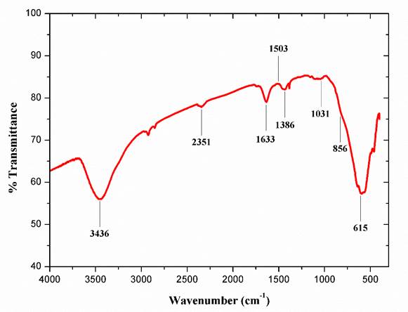
Figure 4 shows the FTIR spectra of the Al2O3 coating removed from the substrate (Figure 2). Amorphous Al2O3 shows a broad peak in the range of 500-900 cm-1. This is due to Al-O stretching mode (750-850 cm-1) and O-Al-O bending mode (650-700 cm-1) (Carmona et al., 2008). There is a broad peak between 3000 cm-1 and 3700 cm-1 which indicates the OH region. Since there is a peak at 1633 cm-1 which can be considered as the H-O-H system (Nakamoto, 2009), while the peak at 3436 cm-1 can be due to the water molecule. Also, there are multiple peaks that represent the characteristic absorption band of alumina that is wide band laying between 900 and 500 cm-1 corresponding to stretching Al-O-Al vibrations (Giri, Sarathi, Chakravarthy, & Venkataseshaiaha, 2004). Stretching vibrations of Al-O and OH are observed at 581 cm-1 and 3415.66 cm-1 respectively. The lack of the H-O-H system in the annealed sample indicates that OH mode at 3414 cm-1 corresponds to hydroxyl species. CH bending vibrations of CH3 are present at 1386 cm-1.
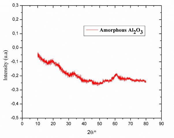
Figure 5 shows the XRD pattern of Al2O3 obtained from the deposited coating, which corresponds to the literature (Reyes, Serrato, & Sugita, 2006). As the coating deposition was made at 370 °C, no characteristic peaks are observed in DRX that indicate the amorphous character of the Al2O3 layer.
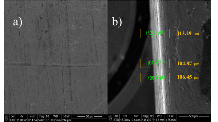
Figure 6a shows SEM micrographs of the alumina surface layer deposited by DLI-MOCVD at 370 °C and a deposition time of 90 min. It can be observed that the layer of Al2O3 is quite homogeneous. Scratches of the polishing process on AISI 1018 steel can be observed, however superficial defects such as pitting, lifting, loss of brilliance, poor adhesion or stains with metallic finishes are not noticed, which confirm the efficient deposition on Al2O3. The thickness of the layer (Fig. 6b) was measured giving approximate values of 100 μm.
4. Conclusions
The DLI-MOCVD procedure allows depositing an amorphous Al2O3 layer at relatively low temperature of 370 °C on AISI 1018 steel substrate. At this low temperature the AISI 1018 surface was not affected and not oxides were detected by XRD. This low temperature allows obtaining an alumina layer thickness of 100 μm approximately.
The result shows that structural properties of the deposited alumina layer would allow to increment performance of the AISI 1018 substrate surface.


 nueva página del texto (beta)

