


 nueva página del texto (beta)
 Inglés (pdf)
 Artículo en XML
 Referencias del artículo
 Enviar artículo por email
 Citado por SciELO
  Similares en
SciELO
Similares en
SciELO 
 Permalink
1. Introduction
One-third of the Earth is covered with oceans. Sensors are responsible for sensing and monitoring the ocean environment. After processing, the node sends the data to the sonobuoy (sensor node for data collection) floating on the ocean surface. The sonobuoys have both GPS and RF transmission modems for communication among the nodes and the sonobuoys (Akyildiz, Pompili, & Melodia, 2005). The sensor nodes are randomly deployed in ocean water in different depths. UWSNs have many applications such as maritime monitoring, security applications, ocean environment monitoring, counting or imaging animals in ocean, extracting oil and gas resources, military and homeland security application, among others.
Underwater communication is done only by acoustic links. The signals that are propagated through the aquatic environment are also another issue. The acoustic signals have low speed V=1500 m/s as compared with radio signals. These signals are not used to transmit the data over a long distance. During the multi hop transmission, the sensor needs more energy for transmitting the data. In this paper, the proposed routing protocol uses a clustering-based approach in which the data are routed from the sensor nodes.towards the sonobuoys by using the clusters. At first, the sensor nodes are selected for cluster heads. Based upon their energy level, the elected cluster heads are selected as cluster heads. Adaptive association algorithms are used in normal sensor nodes with cluster heads are carried to balance the number of clusters (Vasilescu, Kotay, Rus, Dunbabin & Corke, 2005).
The paper is organized as follows: Section II discusses related works carried out by the researchers. Preliminary concepts of clustering and void node recovery strategies are provided in Section III, Section IV provides details about the proposed scheme. The performance evaluation of routing protocols (novel clustered geo-opportunistic routing) is described in Section V. Finally, Section VI presents the conclusion and future scope of this work.
2. Related work
Geographic opportunistic routing (GOR) for underwater wireless sensor networks (WSN) (Coutinho, Boukerche, Vieira, & Loureiro, 2016) is an anycast, geographic (position-based) and opportunistic routing in which the data packets are routed from the sensor nodes to various sonobuoys floating on the sea surface. The node in communication with the void region uses a recovery mode procedure which is based on the depth adjustment of the void nodes. One of the major disadvantages is a very low packet delivery ratio and higher energy consumption (Baranidharan, Sivaradje, & Kiruthiga, 2018). An RCAR- A reinforcement learning-based routing protocol for congestion-avoided underwater acoustic sensor networks (Jin, Zhao, & Su, 2019) has been proposed. In this routing protocol, the next hop forwarder nodes can be chosen based on the residual energy, position information of their neighbor nodes and the current state of the buffer. The reinforcement learning-based function is used to make decisions and converge the optimum route to avoid the overloading of the data packets. This routing protocol also gives optimum routing from the source to the sink nodes. The main advantage of this routing algorithm is that it gives an optimum and converged solution for any changes in acoustic channels. This routing protocol has high computation complexity for choosing the optimum routes.
The energy efficient multipath routing protocol for underwater wireless sensor networks (Khalid, et al., 2019) is widely used to avoid flooding type of routing, and energy consumption is enhanced across the networks. In this routing protocols, E2MR protocols are used to avoid all types of routing which leads to a large number of messages from both sensing and sinks. This routing protocol also enhances the holding time of the data packets depending upon the residual energy. The major disadvantages of this routing protocol are that it does not support the dynamic topology management and that the network stability is decreased.
Distance vector-based opportunistic routing protocols (Guan, Ji, Liu, Yu, & Chen, 2019) exploit the query mechanism which is based on the distance vector towards the sink for each node. The opportunistic routing protocol uses hop by hop transmission strategy and policies. At the second stage, this protocol has complex signaling except the query mechanism will establish the distance vectors are used to transmit the information from the sensor nodes to the sink or monitoring systems. Another advantage of this routing protocol of this light weight signaling uses less signaling overhead. The main disadvantages of this routing protocol is not to avoid the void region, it needs to detour packets along the extremely long detour problems.
Hydrocast: Pressure routing for UWSN (Lee, et al., 2016) is an anycast, hydraulic pressure-based void node routing protocol that routes the sensed data to the sonobuoys on the sea surface. It also has a minimal the number of the transmission in underwater scenario. It also limits the cochannel interference. One of the major disadvantages is that this method does not recover the void nodes (Noh, Lee, Wang, Choi, & Gerla,2016).
A link-state adaptive (LSA) feedback routing protocol (Xie, Cui, & Lao, 2010) is adopted to route the data transmission effectively. To avoid the consumption of energy in sensor nodes are caused by updating the routing table is based on credit based dynamic routing update mechanism. This routing method is not applied for highly dynamic underwater sensor networks.
Void-aware pressure based data routing for underwater acoustic sensor networks (Coutinho, Vieira, & Loureiro, 2015; Yan, Shi, & Cui, 2014) is a simple and robust soft state protocol. It exploist a periodic beaconing signals with direction trails and opportunistic greedy forwarding for routing the packets. The recovery fallbacks of void nodes are not to be considered for data transmission in (Xie et al., 2010; Zuba, Fagan, Shi, & Cui, 2014).
3. Preliminares
3.1. System model
Consider an underwater acoustic sensor networks (UASN) is equipped with aquatic swarm architecture. In this architecture, the N number of mobile sensor nodes in the over and bottom of the sea and sonobuoys are floated over the ocean surfaces. The SEA Swarm architecture model consists of nodes
where NN represents the set of nodes and NS represents the communication range of each and every sensor node. Each and every node is always equipped with N number of sensor devices for different applications and with a very less BW (bandwidth) acoustic modem which is used periodically to report the sensed data to the monitoring system through the sonobuoys. Consider the vertical movement energy and speed values as a depth adjustment mechanism as that work provides information about the various vertical movement speed and cost. Thus, each sensor node has a velocity V = 2.4 m/min at the energy Em = 1500 mJ/m. The sonobuoys NS = S1, S2, .., SN are deployed randomly over the top of the sea surface. Each and every sonobuoy has GPS connection to determine the x, y and z location.
The sonobuoys also have an acoustic modem and radio frequency transceivers. Each and every sonobuoy uses acoustic links to receive and sent data to all other nodes. The RF transceivers are used to forward the sensed data to remote station or monitoring center for further raw data processing.
3.2. Data Packet delivery probability of estimation in underwater scenario
The underwater packet delivery of m bits of any pair of sensor nodes with a distance d, which is used in the next hop forward selection algorithm procedure of this proposed clustering based GEDAR routing protocol. The path loss of a single and unobstructed propagation path due to frequency of signal f is given as
where k - spreading factor, A (f) - coefficient of absorption.
The absorption coefficient A (f) (dB/km) for frequency f (kHz) is described by Thorp’s in the below given formula is
The average SNR over a distance (d) is given as
where Eb and N0 are constants that represent the average transmission, energy required for the sensor nodes and the noise power density (NPD) in a fading and non- fading additive white gaussian noise (AWGN) channel. The probability bit error rate can be evaluated as,
where, Pe(x) is the probability of error for an arbitrary modulation at the specific value of SNR.
4. Design of clustering GEDAR
The energy efficient clustering-based geographic-opportunistic routing with depth-based adjustment topology control for void nodes with communication recovery (GEDAR) for underwater sensor networks consists of four main algorithms:
(1):An enhanced periodic beaconing algorithm used to determine the location of all sensor nodes and floating sonobuoys.
(2):Cluster formation algorithm for the election and selection of cluster heads from the group of normal nodes.
3.2. Data Packet delivery probability of estimation in underwater scenario
Periodic beaconing plays a vital role in any routing protocol. Each node Ni embeds with location of the known sonobuoys Sij together with its location. Each and every node obtains the location information of its neighboring sonobuoy through its periodic beaconing. The size of the periodic beaconing message is
where m and n denote the size of the sequence numbers and ID fields, geographic (position) coordinates, respectively. This enhanced beaconing algorithm is used to broadcast periodic beacons and to handle the received beacons. The nodes generate beacon messages which are embedded with the auto generated sequence number, sensors unique ID and its x, y and z location. The beacons sequence number does not need to be synchronized with the sensors and the sonobuoys. These sequence numbers are used to identify the most recent beacons of each and every sonobuoy. The sonobuoys’ depth information is always omitted from the beacon messages because its vertical movement is always considered to be negligible with respect to its horizontal movement. The pseudocode of the beacon algorithm is discussed in Algorithm 1. The beacon messages are augmented with all the information and sensor nodes sequence numbers, sensor ID, and its position. Those messages are to be broadcasted to all the neighboring nodes.
4.2. Cluster formation algorithm for the CH election and CH selection from the normal nodes
To maximize the network lifetime and reduce excess consumption of energy. The clustering-based GEDAR routing protocol was designed to account the efficient utilization of energy. In this clustering-based approach, all the sensor nodes complete the cluster head election. Then the selection of cluster heads is from the optimal number of normal nodes. The selection of CH from normal nodes is performed based on the distance only. The concept behind this clustered-routing protocol increases the stability of the network. The sensor nodes are randomly deployed over the entire area of the sea surface. The nodes start broadcasting their status information and their position of one with another.
After formation of cluster head election (CHE) procedure, the nodes forms the eligible candidate set. The round (Rnd) value generated for each and every node. The Rnd value is always greater than the threshold value (Rnd TH), then only the node is elected as a cluster head. If the distance (d) value is less than the node selected as a cluster head. Otherwise, the node is always considered as a normal sensor node. The cluster formation algorithm is discussed in Algorithm 2, In this routing protocol, the cluster heads are able to communicate beyond their communication range. This can be achieved by one hop by hop intermediate node by providing relaying services on its residual value. After this process, the node creates its own ID and transmits the message to its neighbor within the deployed communication region. If the two hop member nodes also select their own ID at the end of the selected hop members node IDs. Each CH creates a schedule for its cluster members.
Algorithm 2 Cluster Formation Algorithm
The data packets are broadcasted to their destination by the cluster heads. In this cluster, members transit the data to their CH with a minimal transmission power. The advertisement message of the received signal strength of the data transmission uses a little more energy. All the data are transmitted and received over the CH and members to perform the data aggregation to compress the data. After cluster formation, the CHs broadcast the aggregated data to the next level.
5. Simulation result and discussions
5.1. Simulation setup
The evaluated performance of the C-GEDAR protocol with existing GEDAR. The nodes are deployed randomly over the entire region (500m X 500m X 500m) using an Aquasim simulator which is a special type of simulator for underwater acoustic sensor networks. The sensor nodes varies with a step size of 50 and the number of sonobuoys is five. Those nodes are deployed in the underwater scenario with different depths. The simulation parameters are tabulated in the Table 1. The performance metrics are to be evaluated, various dense and sparse region are to be considered for the simulation. The results are attained by using AQUASIM, they are plotted on the graphs and the conclusions are drawn from them.
5.2. Performance metrics
For a performance evaluation purpose, four metrics are taken into account, packet delivery ratio, energy consumption and end-to-end delay.
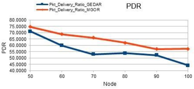
5.2.1. Packet delivery ratio
The PDR is defined as the ratio of the data packets received by the sonobuoys are generated by the sensor nodes. The PDR is defined as
here, the S1 - sum of total number of packets received in the sonobuoys and S2 - sum of received data packets. The efficient transmission of data is always based on the packet delivery ratio Figure 1 shows the results for the packet delivery ratio. As expected, the PDR is comparatively higher than the existing GEDAR routing protocol. This packet delivery ratio is comparatively better for high dense regions. When the density of network increases, more data transmission are needed for data packets delivery for efficient routing protocol.
5.2.2. Average energy consumption
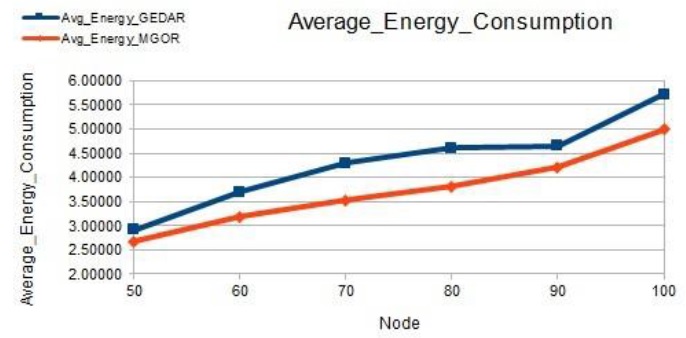
The sensors have the capabilities of physical quality sensing of raw data, data processing and wired or wireless transmitting the collected data to the base stations or monitoring systems by means of single hop or multiple-hop relay. The data transmission always consumes more energy. In the simulation, the average consumption of energy is the difference between the current value and the initial value before simulation. The energy consumption of transmitting data:
Total consumed energy of nodes:
so, the total energy of nodes is equal to the sum of total consumed energy of data receiving and total consumed energy at the time of data transmitting. Figure 2 shows the results for the energy consumed in per received packet in per node of the entire network. As expected, the energy consumption of clustered GEDAR is comparatively lower than the existing GEDAR routing protocol. This energy cost is always related to the adjustment of depth in the void nodes only. As the traffic increases, the energy consumption decreases across the network.
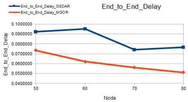
5.2.3. End-to-end delay
Delay indicates the time required for a data packet to be transmitted from source to destination across a network. Figure 3 displays the results concerning the average delay (end to end) of clustered-GEDAR is comparatively much lower for the existing GEDAR routing protocol. This protocol uses cluster routing paradigms to improve the data delivery from one node to another. This protocol moves the void nodes to a new depth, hence the packets are forwarded only to cluster heads. This protocol has an end-to-end delay comparatively lower than the existing GEDAR protocol.
5.2.4. Performance metrics comparison with the existing system
The proposed clustered geographic-opportunistic routing protocol is compared with the existing GEDAR routing protocol in Table 2. The performance metrics are evaluated by using the Aquasim software platform. It is observed that this proposed routing protocol will outperforms than the existing routing protocols in terms of packet de- livery ratio, dropping ratio, latency, end-to-end delay, bandwidth utilization, residual energy and energy consumption. Therefore, this routing protocol will shed some lights on the design of efficient routing protocols for UWSN.
Table 2 Comparison of performance metrics of proposed systems with existing systems.
| Parameters | Existing GEDAR |
Clustered GEDAR |
| Packet delivery ratio | 54.87 | 68.73 |
| End-to-end delay | 47.852 ms | 41.332 ms |
| Bandwidth utilization | 12.5 kHz | 2.44 kHz |
| Throughput | 50.5 kbps | 52.6 kbps |
| Jitter | 37.828 ms | 47.44 ms |
| Average energy consumption | 3.5342 nJ | 2.392 nJ |
| Residual energy | 9550.11 nJ | 9663.14 nJ |
6. Conclusion
This paper evaluates the existing GEDAR and the proposed clustering-based GEDAR routing protocol performance in underwater scenario. More specifically, this paper shows that C-GEDAR outperforms existing work in terms of high packet delivery ratio, lower packet dropping ratio, better average energy consumption and very low delay. This shows that C-GEDAR is the best choice for any practical application at present, the simulated results are expected to shed some light on the design of energy efficacious routing protocol for underwater acoustic wireless sensor networks in the near future. The future scope of this work can be extended to network layer to improve its energy consumption and throughput by chain-based back pressure routing protocol in UWSN.

