


 nueva página del texto (beta)
 Inglés (pdf)
 Artículo en XML
 Referencias del artículo
 Enviar artículo por email
 Citado por SciELO
  Similares en
SciELO
Similares en
SciELO 
 Permalink
1. Introduction
The motion control of robot manipulators is a crucial task due to the wide range of applications in which such robots can be employed (Chua et al., 2003; Markert & Merk, 2009; Meike et al., 2013; Shepherd & Buchstab, 2014). In recent decades, various control algorithms have been used to address this problem, from the classic control to most recent approaches such as Fuzzy Control (FC), Neural Network-Based Control (NNBC), and Sliding Mode Control (SMC) (Arimoto, 1986; Orozco-Soto & Fernández, 2015; Lee & Choi, 2000). The classic control has proven its effectiveness in modern applications. For instance, in Román (2012) a Proportional Derivative (PD) control is designed to solve the regulation problem on a three degree of freedom (DOF) robot manipulator via brain waves, using a computer-brain interface. Another typical controller is the computed torque, a nonlinear controller based on the inverse dynamic model; such controller has been successfully implemented in many works and applications (Jaso & Rosas, 2015; Middletone & Goodwin, 1986; Park & Kim, 1998; Codourey, 1998). However, these techniques still carry some significant disadvantages in their design. For example, they do not consider the disturbance rejection in their structure. Besides, they tend to demand high gains in the control actions to have a good performance in the presence of disturbances.
Some modern control methods have been studied to develop and implement robust controllers in different robot manipulators, even without the need to know the system dynamic model. Such is the case of Meza (2003), where a fuzzy adaptive control based on observers is designed to identify and control nonlinear systems. For this method, the control actions are defined based on linguistic rules provided by an expert operator. However, although it would produce a reliable control law based on human experience, it could also be an inconvenience in the absence of such an expert (Sugeno & Takagi, 1993).
Sliding Mode Control (SMC) is an effective, robust nonlinear control technique (Shtessel et al., 2014; Sira-Ramírez, 2015) since it provides insensibility to coupled dynamics and robustness in the presence of disturbances. Therefore, its study has attracted attention in the field of robotics. In Piltan & Sulaiman (2012), a review of SMC in robotics shows recent attempts to implement SMC in robot manipulators. The main problem in using conventional SMC in electro-mechanical systems is the discontinuous nature of its control law, which produces actuator saturation, heat in mechanical parts, and the so-called chattering effect (Utkin et al., 2017). Several methods have been developed to attenuate or eliminate these effects in conventional SMC. Some exciting approaches include combining SMC with artificial intelligence techniques, producing hybrid variable-structure controllers focused on solving the motion control task in robot manipulators (Amer et al., 2011; Corradini et al., 2012; Vijay & Jena, 2017; Yu et al., 1999).
A different proposal is the use of the Second Order Sliding Mode Controllers (SOSMC). Within these control algorithms, we can find the Super-Twisting (ST) control, which was initially designed to be a continuous control law, capable of compensating smooth bounded perturbations (Levant, 1993; Levant, 1998; Moreno, 2009). This controller is widely used to replace discontinuous SMC with a continuous control law without losing robustness properties. Therefore, its use in robot manipulators has recently started to be explored (Trejo, 2018; Hernandez et al., 2011; González et al., 2007).
This paper aims to propose an ST controller capable of achieving an acceptable performance in trajectory tracking tasks for a 4 DOF robot manipulator, incorporating system robustness against parameter uncertainty, unmodeled dynamics, and external forces. Additionally, the stability conditions for the tuning procedure of the controller are presented. A PD with dynamic compensation (PD+) controller is designed for comparison purposes. A computational tool is used to test the performance of the proposed controllers in the trajectory tracking problem, and then the results are discussed and compared.
The remainder of the paper is organized as follows. Section two describes the problem for which we propose a solution. Section three describes the considerations taken into account about the manipulator configuration, along with the dynamic model of the system. Section four presents the structure of both control algorithms; in addition, the design and tuning procedure are detailed for each controller. In Section five, we exhibit the simulation results of each controller and present the discussion about them. Section six contains the conclusions derived from the realization of this work.
2. Methods, techniques, and instruments
Problem formulation
The motion control problem of robot manipulators carries several issues related to the effectiveness of the implemented controllers and the manipulator’s capability of executing some specific tasks. For instance, the efficacy of model-based controllers directly depends on the accuracy of the system model. However, in some cases, there may be discrepancies between such model and the physical system, mainly due to parameter uncertainty and unmodeled dynamics; these discrepancies may diminish the efficacy of these controllers. Furthermore, robot manipulators that operate away from controlled environments, such as the ones attached to explorer vehicles for space and deep-water missions, are usually submitted to unknown external forces, which affects the performance of the tasks assigned to the robot manipulator.
The described problems above can be treated as one if we group parameter uncertainty, unmodeled dynamics, and unknown external forces as a single perturbation term. This problem is known as disturbance rejection and can be addressed using a robust control strategy.
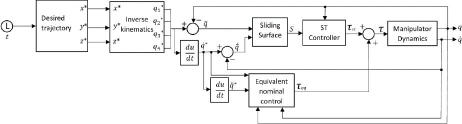
Therefore, the robust control strategy has relevance because it allows decreasing the effects of the mentioned features. Moreover, with this strategy, it is possible to obtain good performance for the robot manipulator tracking control problem. This work presents a solution for this issue through a sliding-mode-based control law known as ST controller. The methodology of the present work illustrated in Figure 1.

Mathematical model
Let be the 4-joint robot manipulator shown in Figure 2a (without end-effector). Consider the coordinate frames fixed to the manipulator (see Figure 2b). The dynamic model is obtained using Lagrange’s equations, where the Lagrangian

Then the kinetic energy function
In addition, Rayleigh’s dissipation function is introduced into Euler-Lagrange’s dynamic equations, obtaining:
Where:
Thus, four dynamic equations correspond to the torques delivered by the actuators and can be expressed as follows:
Where:
Manipulator parameterization
The control algorithm design requires the parameterization of the manipulator physical parameters used in the dynamic model. A manipulator design is made in the CAE-CAD SolidWorks software with the actual values of the structure dimensions and considering aluminum alloy 1060 as the primary construction material.
By using the virtual model of the manipulator, it is possible to analyze the physical properties of each of the links that make up the manipulator and thus obtain the parameters that describe it.
Considering that
It is necessary to assign a new reference frame to each link based on the rules of Denavit Hartenberg’s method. The physical properties obtained are the total mass of each link, the entire length of each link, the center of mass of each link concerning the new reference frame, and the inertia tensor of each link to the new reference frame.
The viscous friction parameters which are present in the servo motors coupled to each joint are considered. Such friction values are obtained from a previous system identification made for the engines used in a manipulator with similar characteristics to the one studied in this work (Corke, 2017). The results of the parameterization performed are grouped in Table 1.
Table 1 Parameters of manipulator robot.
| Parameter | Notation | Value | Units |
|---|---|---|---|
| Link length 1 |
|
0.030 |
|
| Link length 2 |
|
0.124 |
|
| Link length 3 |
|
0.128 |
|
| Link length 4 |
|
0.160 |
|
| Center of mass for Link 1 |
|
[0 -0.013 0] |
|
| Center of mass for Link 2 |
|
[-0.056 0 0] |
|
| Center of mass for Link 3 |
|
[-0.075 0 0] |
|
| Center of mass for Link 4 |
|
[-0.104 0 0] |
|
| Link mass 1 |
|
0.069 |
|
| Link mass 2 |
|
0.044 |
|
| Link mass 3 |
|
0.097 |
|
| Link mass 4 |
|
0.203 |
|
| Inertia tensor of link 1 |
|
|
|
| Inertia tensor of link 2 |
|
|
|
| Inertia tensor of link 3 |
|
|
|
| Inertia tensor of link 4 |
|
|
|
| Viscous friction coefficients |
|
|
|
The notation used in Table 1 is, centers of mass correspond to
a. PD+ control
The PD+ Control for trajectory tracking is a robust passive computed torque controller (Han et al., 2020), which requires the exact knowledge of the manipulator’s dynamic model to be implemented (Kelly et al., 2006; Reyes, 2011), that is, of
Where:

The gain tuning of the PD+ controller does not depend on the manipulator model nor the task assigned to it. It is usually suggested to be performed manually and based on the designer’s knowledge (Kelly et al., 2006; Reyes, 2011). To propose a tuning procedure for the PD+ controller, we assume that the control law compensates the nonlinear nature of the manipulator at some instant of time, then we can describe the manipulator dynamics of the form:
The linear system described in (6) is used for tuning purposes only and can be represented by the following block diagram:

The closed-loop equation is:
The selection of
Thus,
The controller gains,

b. Control Super-Twisting control
Consider the existence of a Lipschitz disturbance term, the dynamic model of the robot manipulator is rewritten as:
Where:
The purpose of SMC is to force the sliding surface dynamics to reach the value of zero in a finite time and keep it at zero thereafter, i.e.:
Once this is accomplished, the controlled dynamics are described by:
The solution of (14) is:
Thus, it is shown that the position error and its derivative converge to zero asymptotically. Deriving the sliding surface, we obtain:
Where it is clear that:
Then, substituting (11) into (17), we have that:
We propose the following control law:
Where:
Thus,
Equation (21) is the equivalent control and indicates that the second term of the control law should be equal to the negative of the disturbance term to assure the system’s robustness. However, this control action usually cannot be implemented, since it depends on the disturbance
To satisfy condition (13), the use of an SMC with the equivalent nominal Control is proposed, providing robustness to the system in the presence of disturbances. The proposed controller is a Super-Twisting (ST) control. Then the control law is rewritten as:
Where:
With
Figure 6 depicts the block diagram of the ST controller for the robot manipulator.
Substituting (22) in (18), we obtain:
If
Thus,
At this point, the design problem is reduced to the setting of the parameters
The stability proof for this tuning procedure is not developed in this paper. In exchange, we present sufficient conditions for the controller to be stable in finite time. In the interest of doing so, we use the stability proof for Super-Twisting parameter setting shown in Seeber & Horn (2017), from where we extract the following. Let us define the below system:
Where:
Theorem 1: The system (30)-(31) is stable in finite time if its parameters satisfy the following conditions (Seeber & Horn, 2017).
Comparing (27) and (28) with (30) and (31), we can see that the sliding surface corresponds to the system form referred to in Theorem 1. Thus, such a theorem is valid to analyze the stability of the sliding surface. Observe that the parameter setting (29) proposed in (Levant, 1998) satisfy condition (32), which proves the finite-time stability of the ST controller with the use of these gains. Therefore, the sliding surface designed in this work is stable in a finite time by the following control law:
To proceed with the setting of the gains
Finally, the design parameter
Remark: Note that the proposed sliding mode controller is capable of
compensating asymptotically Lipschitz uncertainties/perturbations. In the case
of a discontinuity in the perturbation vector
Inverse Kinematics
We use inverse kinematics to link the robot manipulator’s position and orientation in the workspace with the robot manipulator joint positions. In this paper, we decide to employ a geometric approach to obtain the inverse kinematics of the robot manipulator. Furthermore, we choose to restrict the inverse kinematic solution to the elbow-down solution.
Consider Figure 7, which represents the robot manipulator links and where the


The following homogenous transformation matrix denotes the position and orientation of the end effector:
Where:
From Figure 7 and equation (36), we define the position vector
Then,
From Figure 7 and Figure 8, we define the following parameters:
Where:
Then, substituting equation (42) in equation (41), we obtain:
From which we derived the following:
Then,
Similarly, from Figure 8,
Similarly, to compute
Then, equation (51) is rewritten as:
Finally,
Therefore, the solution to the inverse kinematics is defined by equations (38), (46), (49), and (54), which are grouped in a vector that denotes the actual joint positions of the robot manipulator given a homogenous transformation matrix for the robot manipulator end effector:
Robot task
The trajectory proposed in this work is intended to be smooth in time and be reachable by the end effector within the workspace of the robot manipulator. Such trajectory in the workspace is described by the following equations:
And finally, the variable
Which denotes the desired position of the robot manipulator end effector, and where the time variable

The orientation of the robot end-effector can be defined in terms of the
Finally, we can group both, the position vector, and the rotation matrix in the following homogenous transformation matrix:
Thus, for each value of
In summary, the robot’s end-effector must follow the trajectory and orientation described in (58). The inverse kinematics equations are thus used to find the necessary angles in each joint. Therefore, the reference values to be entered into the controller are obtained. Figure 10 shows the block diagram to get the desired angles for the robot’s joints.

Numerical simulations
The designed control algorithms were tested in Matlab-Simulink, using the robot manipulator’s dynamic model to evaluate the performance of each controller for a trajectory tracking task. Such desired trajectory was designed to be smooth and differentiable in time.
As it was pointed out before, the perturbation term must be Lipschitz. Taking this into account, we propose
The performance of each control algorithm in both joint space, and workspace, for the trajectory tracking task in the presence of perturbations are shown in Figure 11 and Figure 12. From these figures, the PD+ Control is evidently more affected by the disturbance force than the Super-Twisting Control.


In addition, in Figure 13, we present the required torque by each controller. Note that the demanded torque by the Super-Twisting Control is a continuous function (see Figure 13b). Furthermore, it is essential to point out that part of the tunning criteria considers that the control outputs were bounded within a range corresponding to the actual value of torque given by commercial actuators.

3. Results and discussion
To provide an analytical analysis for the obtained results, we also include the position error achieved for each controller in both joint space and workspace. From Figure 14, we observe that the maximum error in the robot joint’s desired trajectory is bounded by

Additionally, we also include an error analysis for the joint space based on three error metrics named Incremental Error (IE), Incremental Absolute Error (IAE), and Mean Square Error (MSE), which are defined as follows:
Where: N denotes the total number of samples, and i represents the joint number of the manipulator with


Furthermore, from Table 2, we observe that the final value of IAE is significantly smaller for the Super-Twisting controller, up to 29 times smaller in joint one than its PD+ counterpart. Finally, the MSE value is lower with the Super-Twisting controller on most joints.
Table 2 Error Metrics (EM) obtained with PD+ and ST controllers [
| EM | PD+ Control | Super-Twisting controller |
|---|---|---|
| IE |
|
[ |
| IAE |
|
|
| MSE | [3 |
[ |
Bearing in mind that the ultimate goal of a robot manipulator is to execute an assigned task on its workspace, it is also essential to analyze Figure 18, from which we can see that the maximum position error achieved in the workspace by the PD+ Control in the presence of perturbations is bounded by

Furthermore, to illustrate Super-Twisting stability, the behavior of the sliding surface is shown in Figure 19. From such a graph, we observe that the sliding surface reaches the origin in a finite time and stays at zero thereafter, satisfying condition (13).

4. Conclusions
The present paper describes the development of a Super-Twisting controller applied to the motion control of a 4 DOF robot manipulator and its comparison with a classic PD+ control. From the obtained simulation results, we can state the following.
PD+ Control can solve the trajectory tracking problem. Nevertheless, its performance was affected by disturbances, which compromises the realization of the assigned task. Considering that the PD+ Control is a high gain controller, the disturbance rejection problem might be solved by increasing the controller gains until we obtain a complete disturbance compensation. Despite this may be seen as a possible solution, it could be conflicted with the physical limitations of the actuators.
On the other hand, from the position error plots, we can conclude that the Super-Twisting controller accomplished an adequate compensation of the disturbance term. Consequently, its performance was not diminished, making this controller suitable for high accuracy tasks even in the presence of perturbations. One main limitation of the SMC is the discontinuous nature of its control laws, which are usually hard to implement in electro-mechanical systems. However, as it was shown, in the case of the Super-Twisting, its control action is a continuous function. Therefore its physical implementation might be possible.
Furthermore, it should be noted that the actions of the ST control were limited to the actual value (same range as the PD +) of the commercial actuators torque, achieving an error (in the presence of disturbances) seven times less than the obtained with a PD +.
Currently, the problem of tracking trajectory in the presence of disturbances has been solved by various methods. However, our proposal shows in detail the stability conditions for the controller adjustment procedure. We use a Lipschitz-type function

