


 nueva página del texto (beta)
 Inglés (pdf)
 Artículo en XML
 Referencias del artículo
 Enviar artículo por email
 Citado por SciELO
  Similares en
SciELO
Similares en
SciELO 
 Permalink
1 Introduction
The electrospinning technique can fabricate several types of organic, inorganic, or composite fibers and nanofibers. By controlling the physicochemical parameters of both the spinnable solution and the ambient parameters during the fabrication process, it is possible to generate smooth, porous, hollow, filled, ribbonlike, branched, single, core-shell fibers and nanofibers, among other morphologies and architectures. Both fiber diameter and morphology allow adjusting their properties [1]. Electrospinning has been proven capable of processing several polymers and composite solutions into continuous fibers to fabricate large membranes. A fundamental requirement is to focus on polymer selection and its physicochemical properties such as molecular weight, viscosity, conductivity, and thermal [2]. Besides that, other factors that can influence fiber morphology and their properties are the electrospinning parameters such as distance to the collector, voltage, feed rate, etc. [3], and the ambient conditions (humidity, temperature, pressure, etc.) [2]. Specifically, relative humidity (RH%) could affect the morphology, structure, and diameter size distribution of the fibers [4,5]. Several biopolymers or synthetic polymers could be selected as co-spinning agents during composite fiber fabrication as a matrix or to reinforce the material where the phase or element of interest may intercalate [6]. One of these polymers is the poly(ethylene oxide), PEO, used to facilitate polymer entanglement during electrospinning production due to its linear structure with flexible and long chains [7]. Cerium, in turn, is the most abundant lanthanide found on Earth, which shows stability at both trivalent and tetravalent states. It has been used in fuel cells, optical devices, gas sensors, catalysis, ultraviolet absorbers, hydrogen storage materials, polishing materials, and biomedical applications [8]. William et al. reported that Ce ions increase the electrical charge and evaporation rate during the Electrospinning process in PEO solutions [9]. Meanwhile, mix-ups of cerium (III) nitrate hexahydrate and poly ethylene glycol inhibit the corrosion of a cathode during an immersion period of at least 30 min [10]. Likewise, the interaction of Ce dopant exhibits a prolonged antimicrobial activity due to its dual oxidation state. It has low levels of toxicity in fibroblasts, so its cutaneous use is plausible [11]. This work establishes the experimental conditions to fabricate single and core-shell fibers of PEO doped with cerium chloride hexahydrate III (Ce) at several concentrations in two ambient humidities.
Their morphology, average diameter, composition, and thermal properties were analyzed using scanning electron microscopy (SEM), atomic force microscopy (AFM), Fourier transform infrared spectroscopy (FTIR), differential scanning calorimetry (DSC), and thermogravimetric analysis (TGA).
2 Materials and Methods
2.1 Materials
Polyethylene oxide (PEO, (-CH2CH2O-)n, MW = 6000,000 g/mol), cerium (III) nitrate hexahydrate (Ce, Ce(NO3)3 6H2O, MW = 434.22), and acetic acid (Ac.Ac., CH3COOH) were purchased from Sigma-Aldrich. We used deionized water grade miliQ (ddH2O) with electrical resistivity of 18.2 MΩ cm. All reagents were analytical grade and used without any purification.
2.2 Preparation of single and core-shell fibers
Acetic acid at 10 %v/v was used to dissolve 4 % of PEO under vigorous stirring
for 2 h at room temperature to prepare the core solution of the bilayer and
single fibers. After a minimum of 12 h, Ce at 0, 0.5, 2.0, or 3.5 % was added to
the previous solution and vigorously stirred at room temperature for 1 h. The
outer layer of the core-shell samples was made only of 4 % PEO solutions. A
homemade electrospinning system manufactured the samples in two relative
humidity ranges (RH = 27-32% and 47-52%) monitored with Labview® Software
[2,5,8]. Single (21G×30 mm) or core-shell (21G×30
and 18G×40 mm) spinnerets were used to fabricate them (Fig. 1). The aqueous polymer solutions of interest were
injected with a programmable pump (KD ScientificTM, model: 780100V)
loaded into a single or double syringes system. The needle tip was connected to
the anode of the voltage power supply (Gamma High Voltage Research, model:
ES60p-20W/DAM), whereas the cathode was attached to an aluminum collector of
10×10 cm. The values of the variables: electrode separation (d
= 14 cm), voltage (V = 20 — 25 kV DC), core infusion rate (

Table I summarizes the sample names, relative humidity, and the molar ratio used during the fabrication of all-fiber samples by electrospinning. PEO/Ce indicates the relation between polymer and dopant. The samples were named PEOCeXYZ, where X is s (single) or d (core-shell) sample type, Y corresponds to the percentage of relative humidity used inside the chamber during the fabrication (H = 47 — 42 and L = 27 — 32 %RH), whereas Z is the concentration of Ce used (0, 0.5, 2.0, or 3.5 %).
Table I Sample nomenclature of fibers manufactured by electrospinning technique. The out layer of all core-shell samples is PEO at 4 %. Letter s or d refers to single and core-shell fiber, H or L to 47-52 and 27-32 %RH, and 0, 0.5, 2, or 35 refer to the concentration of the Ce molar ratio used (0, 0.5, 2.0, and 3.5 %).
| Type of fiber |
RH (47-52 %) |
RH (27-32 %) |
Molar ratio |
|---|---|---|---|
| Single | PEOCeHs0 | PEOCeLs0 | PEO/Ce (0%) |
| Single | PEOCeHs05 | PEOCeLs05 | PEO/Ce (0.5%) |
| Single | PEOCeHs2 | PEOCeLs2 | PEO/Ce (2%) |
| Single | PEOCeHs35 | PEOCeLs35 | PEO/Ce (3.5%) |
| Core-shell | PEOCeHd0 | PEOCeLd0 | PEO/Ce (0%) |
| Core-shell | PEOCeHd05 | PEOCeLd05 | PEO/Ce (0.5%) |
| Core-shell | PEOCeHd2 | PEOCeLd2 | PEO/Ce (2%) |
| Core-shell | PEOCeHd35 | PEOCeLd35 | PEO/Ce (3.5%) |
2.3 Characterization
The morphological characteristics of the samples were visualized with scanning electron microscopy (SEM, JSM-6610LV) in SEI mode and atomic force microscopy (AFM, XE7 de Park Systems) in tapping mode with slow scanning speed. The average fiber diameter was calculated using ImageJ software by measuring 100 fibers in 10 SEM micrographs (X5,000) of each sample analyzed. Fourier Transform infrared spectroscopy spectra were recorded on a Thermo Scientific spectrometer (model Nicolet Isso FT-IR) with ATR apparatus, in the 4000-500 cm-1 range, with a 4 cm-1 and 32 scans per minute. Thermal properties were recorded by differential scanning calorimetry (DSC, Q2000 TA Instruments), with a heating rate of 10o/min from 25 to 550.
3 Results and discussions
To examine the spinnability of PEO/Ce solution and the influence of the addition of
Ce (0, 0.5, 2, and 3.5 %) during the fabrication of single and core-shell fibers, a
group of variables to fabricate polymeric scaffolds were experimentally established.
Relative humidities (27-32 and 47-52 %RH), electrode separation (d
= 14 cm), voltage (V = 20 — 25 kV DC), core infusion rate (
3.1 Morphological analysis
Single (PEO/Ce) system. In the case of single fiber scaffolds, the samples PEOCeLs0 (Ce 0 %, 27-32 %RH), PEOCeLs05 (Ce 0.5 %, and 27-32 %RH), and PEOCeHs05 (Ce 0.5 %, 47-52 %RH) showed the formation of the Taylor cone and no dripping of the needle (Fig. 2).
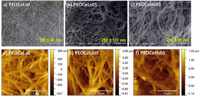
Figure 2 SEM (upper row) and AFM (bottom row) images of single samples: a) and d) PEOCeLs0, b) and e) PEOCeLs05, and c) and f) PEOCeHs05.
Undoped PEO fibers ((PEOCeLs0 sample) presented their characteristic random cylindrical shape (Fig 2a)) [12,13,14]. In turn, fibers doped with Ce at 0.5 % allow the fabrication of single fibers, as previously reported [15]. PEOCeLs0 and PEOCeLs05 single fiber composites with the lowest range of Ce exhibited a change of morphology from cylindrical fibers (Fig 2c)) to 2D-mesh (Fig 2b)). Depending on the application, 1D or 2D fibers are desired. AFM topography images revealed a detailed morphology of segmented cylindrical shape for PEOCeLs0 (Fig 2d)), segmented bi-fibrillar in PEOCeLs05 (Fig 2e)), and cylindrical fibers with two diameters in PEOCeHs05 (Fig 2f)). Despite the relative humidity used during the fabrication process (27-32 or 47-52 %RH), PEO/Ce solutions with a higher dopant amount up to 0.5 % were not spinnable.
Core-shell (PEO-PEO/Ce) system. To generate a lower liquid-liquid interfacial tension between the inside and the outside to create thinner fibers, we used the same miscible acetic acid solution as a solvent [16,17] of the PEO polymer. Several authors have prepared fibers from two immiscible polymers but miscible solvents, obtaining highly porous structures [18]. Figure 3 shows the PEO-PEO/Ce samples fabricated by coaxial electrospinning.
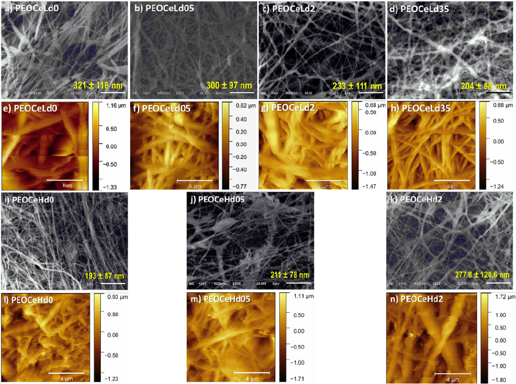
Figure 3 SEM (upper and third rows) and AFM (second and bottom rows) images of core-shell samples at 27-32 and 47-52 relative humidities: a) and e) PEOCeLd0, b) and f) PEOCeLd05, c) and g) PEOCeLd2, d) and h) PEOCeLd35, i) and l) PEOCeHd0, j) and m) PEOCeHd05, k) and n) PEOCeHd2.
In all cases, primarily cylindrical fibers or 2D-mesh were found and, in some cases, some beads (Fig 3j)). Depending on the application of fibers, a specific morphology is desirable. AFM topography images showed that the increase of Ce dopant softens and homogenizes the diameter of the threads in environments with 30 %RH. It was found that a shell capping of PEO on PEO-Ce fibers helps to increase the Ce concentration from 0.5 to 2 % under a 47 — 52 %RH, whereas if moisture decreases to 27 — 32 %RH, the Ce concentration ranges from 0.5 to 3.5 %. In particular, when a 3.5 % of Ce was used (at 47 — 52 %RH), the jet showed dripping, and high instability, and the Taylor cone did not form. Sharma et al. found 3.5% of Ce amount as the optimum amount in the case of PVA-chitosan composites [19]. The Ce amount equal to 2% produces continuous and bead-free samples for the two moisturizers used in this work.
Figure 4 shows the AFM phase and SEM micrographs (X20,000) of fibers with the highest (PEOCeLd35, 3.5 %, Fig 4a)-b) and the lowest (PEOCeLd0, 0 %, Fig 4c)-d) amount of dopant fabricated at 27-32 %RH. AFM phase imaging is a powerful tool to determine the presence of two materials during composite material formation, mainly in plane surfaces [20]. Here, it was applied to show the fibers bilayer when was used the same solvent on core and shell solutions for the fabrication process (Fig 4c), black arrow) [21]. AFM phase images of Fig 4a) and c) correspond to the AFM morphology ones of Fig 3e) and h).
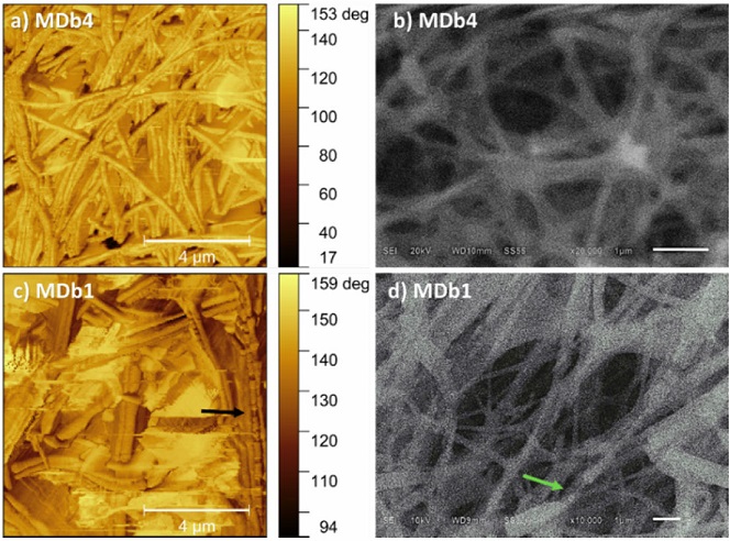
Figure 4 AFM phase (left column) and SEM (right column) images of core-shell samples: a-b) PEOCeLd35, and c)-d) PEOCeLd0.
Average diameter of single and core-shell fibers. Figure 5 compares the average diameter (p < 0.05) of both types of fabricated samples: single and core-shell ones manufactured at two ranges of humidities (27 — 32 and 47 — 52 %RH).
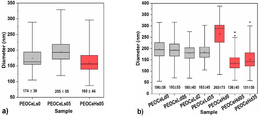
Figure 5 Average diameters of a) single and b) core-shell fibers fabricated at two ranges of humidities (27-32 and 47-52 %RH).
PEOCeLs0 and PEOCeLs05 single fiber composites (Fig 5a)) increased on their average diameter when the relative humidity was decreased to 27-32 %RH, independently of the presence of Ce. A slightly lower average diameter was shown when moisture increases from 27-32 to 47-52 %RH (samples PEOCeLs05 and PEOCeHs05), which agrees with other authors [5,8]. Due to the PEO hydrophilicity character, increasing water molecules during the fabrication process increases the polymer jet’s wettability, leading to small diameter fibers [22]. The determination of the average diameterof single samples is provided as supplementary information (Fig. 9). Figure 5 corresponds to the core-shell fibers fabricated at two humidity amounts in the atmosphere during the process of electrospinning (27-32 and 47-52 %RH). In this case, the linear chain of PEO or its hydrophilic character does not favor the formation of smaller diameter fibers when the water amount in the atmosphere increases (PEOCeLd0 and PEOCeHd0 samples). However, the Ce dopant in the fabrication solution, independent of the ambient water content, leads to thinner fibers. At higher humidity in the ambient (47-52 %RH), adding the lower amount of Ce results in the thinnest fibers (Fig 5b), red boxes). It was reported that the presence of metal ions reduces both the diameter of the threads and the number of imperfections [23]. At the same time, the higher percentage of water molecules in the complexes would allow the formation of hydrogen bonds between the polymer chains [24]. The average diameter of core-shell samples is supplementary information (Fig 10). Then, as other authors have also obtained [2,6,11], we observed the dependency of ambient relative humidity during the fabrication process versus fiber formation. A schematic proposal of single and core-shell fibers and the ionic interaction between the chain of PEO and cerium (III) nitrate hexahydrate is proposed in Fig. 11.

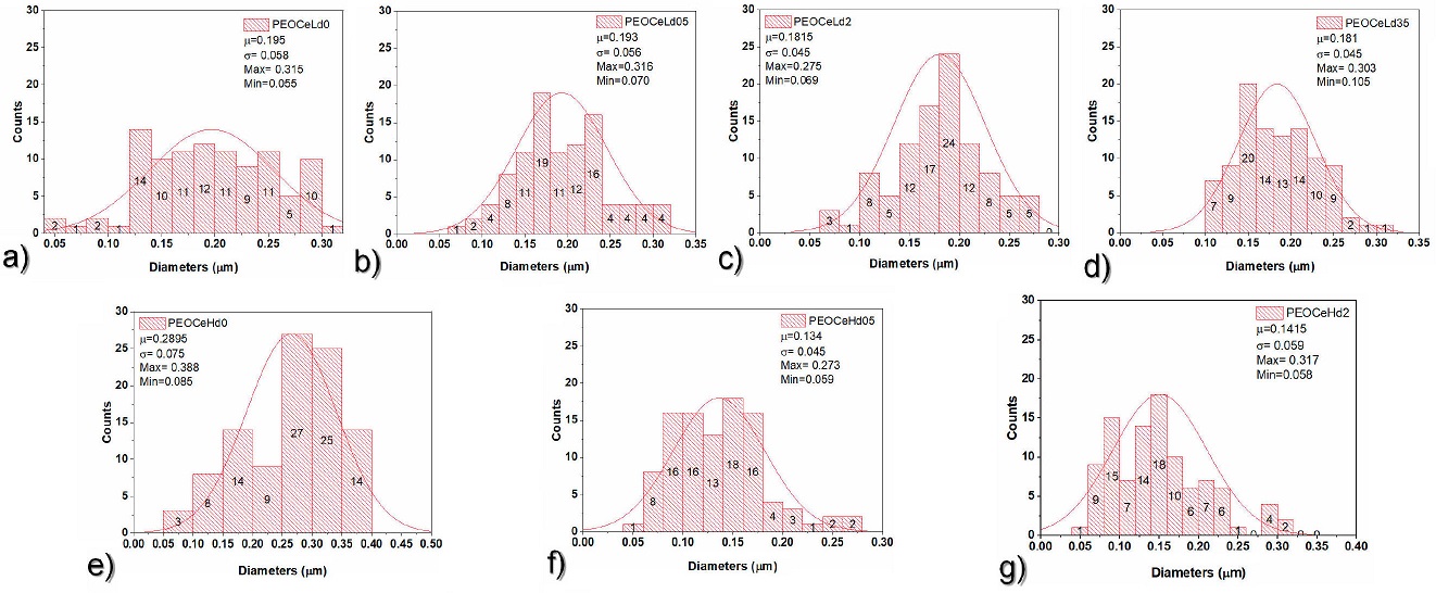
Figure 10 Average diameter of core-shell samples. a) PEOCeLd0, b) PEOCeLd05, c) PEOCeLd2, d) PEOCeLd35, e) PEOCeHd0, f) PEOCeHd05, and g) PEOCeHd2.

3.2 Compositional Analysis
Single PEO/Ce system. The FTIR spectra were used to determine the molecular interactions for PEO/Ce single fibers. Figure 6 shows the spectra of fiber precursors (Fig. 6a)) and those corresponding to PEO-Ce single fibers (Fig. 6b)). Two central dominant absorption regions are recognized in all PEO spectra: the first between 3000 and 2700 cm-1 and the second from 1500 to 750 cm-1 [25].
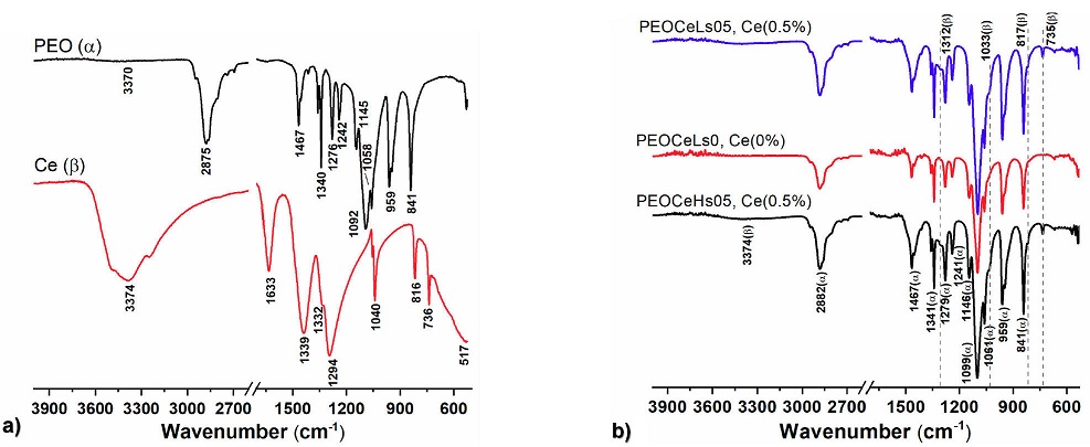
Figure 6 FTIR spectroscopy profiles of a) PEO and Ce precursors and b) PEOCeLs0, PEOCeLs05, and PEOCeHs05 electrospun samples.
The width attenuated band centered around 3370 cm-1 corresponds to
hydroxyl groups (OH-) (Fig. 6b). The band
at 2875 cm-1 in the precursor suffered a redshift of 4
cm-1 assigned to symmetric and asymmetric C-H stretching modes of
methyl and methylene groups (-CH3, -CH2-) in all
fabricated samples. Two different molecular conformations of PEO, known as
helical (H-structure) and transplanar structures (T-structure), have been
reported [26,27,28] in the case of casting PEO films.
Adding water to PEO makes complexes with a planar zigzag structure (T)
[26]. FTIR result showed, in all cases, a T
structure. The bands at 1467, 1340, 1279, and 1242 cm-1 were produced
due to the wagging and twisting B-vibrations of the
-CH2- group, respectively, whereas 959 and 841 cm-1
correspond to the -CH2- group under rocking vibration. We used the
B-vibration of the -CH2- group at 1467
cm-1 as a reference since it has been suggested that neither the
intensity nor the position is affected by the conformation and crystallinity of
PEO [29,30]. The vibrational bands at 1340, 1279,
959, and 841 cm-1 were characteristic of the H structure, whereas
1340, 1242, and 959 cm-1 were characteristic of the T structure
[26]. In turn, 1145, 116, and 1062 cm-1
bands were associated with C=O asymmetric stretching vibration of secondary and
primary alcohols, indicating the crystallinity of PEO. The redshift of about 17
cm-1 at 1099 cm-1 peak suggests that chain-chain
interactions may be due to a restraint stretching vibration of the -C-O-C- group
in the main chain [31]. On the other hand, Fig. 6a also shows the cerium (III) nitrate hexahydrate (Ce)
precursor FTIR spectra. In particular, the broad OH- band around 3374
cm-1 and the NO3-(H2O)6 ions at
A (1050-1550 cm-1) and B (1550-1700 cm-1) vibrational
bands were observed. Band A at 1340 and 1349 cm-1 corresponds to the
NO3-antisymmetric stretching mode
Core-shell (PEO-PEO/Ce) system. Figure 7 shows the FTIR spectra of the PEO-PEO/Ce electrospun samples at two different relative humidities. As in the case of single fibers, all absorbance bands correspond manly to the PEO polymer. The characteristic broadbands of Ce-O modes at 1312, 1033, 817, and 735 cm-1 were found. A higher transmittance is appreciated when the Ce amount increases, particularly at 735 cm-1 (Fig. 7).

3.3 Thermal analysis
The determination of future applications of the membranes depends, among others,
on their thermal properties. Figure 8 shows
the thermal analysis of all electrospun membranes. Differential scanning
calorimetry (DSC, Fig. 8a)) was carried out
to determine the effect of Ce dopant on the crystallinity of single and
core-shell PEO samples. Figure 12
corresponds to the obtained individual endothermal temperature


In all fiber samples, an increment of Tm is observed independently of Ce amount.
Single fibers (Fig. 8a)) showed a shift of
~6oC when they were electrospun, whereas core-shell ones
presented increments of ~1.9 and ~7.7o for the samples with the
higher and lower amount of Ce (PEOCeLd35 and PEOCeHd05), respectively. Single
fibers have shown negligible changes between doped and undoped samples or
ambient water molecules during the fabrication process (% RH). By its side in
core-shell fibers, a relationship of Tm with the concentration of Ce and ambient
water molecules (% RH) is observed. Samples fabricated with 27-32 %RH showed an
increase in their
Table II Thermal properties of single and core-shell samples, assessed by DSC and TGA.
| Sample | Tm(oC) |
|
|
|
|
Total % lost |
|---|---|---|---|---|---|---|
| 175 (1.71) | ||||||
| PEOCeLs05 | 75.4 | 101.3 | 54.2 | 182 (1.14) | 402 (76.6) | 81.74 |
| 244 (2.29) | ||||||
| PEOCeLs0 | 75.3 | 103.2 | 52.7 | — — | 403 (93.06) | 93.06 |
| 166 (0.82) | ||||||
| PEOCeHs05 | 74.2 | 99.8 | 53.4 | 184 (2.21) | 402 (76.10) | 80.39 |
| 228 (1.26) | ||||||
| 174 (1.22) | ||||||
| PEROCeLd35 | 71.3 | 70.3 | 54.9 | 185(4.48) | 398 (63.86) | 70.56 |
| PEOCeLd05 | 75.4 | 103.1 | 55.1 | 222 (0.89) | 404 (84.04) | 84.93 |
| PEOCeLd0 | 75.3 | 105.9 | 53.8 | 402 (91.61) | 91.61 | |
| 181 (1.19) | ||||||
| PEOCeHd2 | 75.6 | 91.8 | 58.3 | 185 (2.09) | 398 (71.33) | 74.61 |
| PEOCeHd05 | 77.1 | 106.2 | 56.8 | 211 (1.34) | 403 (88.22) | 89.56 |
| PEOCeHd0 | 79.2 | 106.7 | 54.2 | — — | 401 (92.32) | 92.32 |
It has been reported that a PEO fiber contains several fibrils of fibrillar
crystals and amorphous regions [36,37]. The addition of
Ce(NO3)36H2O induces the increment of
crystallinity of single and core-shell samples until 2 %, indicating that there
is a cut-off dopant concentration above which
The thermogravimetric analysis of undoped and doped PEO single and core-shell fibers is presented in Fig. 8b), whereas the first derivative of TGA (DTGA) is supplied as supplementary information (Fig. 13). Doped PEO single fibers DTGA (PEOCeLs05 and PEOCeHs05, Figs. 8b and 12a) revealed three processes of weight loss of ~4.3 and ~5.1 %, respectively, between 150 and 275 that could correspond to loss of water, inorganic and organic materials decomposition from PEO and NOx [38,39,40]. The highest weight loss of doped and undoped samples occurs ~400oC, and is related to the PEO [35]. Then, adding Ce dopant enhances the thermal properties of the PEO single fibers and consequently a lower loss of mass, independently of the water concentration in the atmosphere during the fabrication. By its side, core-shell samples PEOCeHd05, PEOCeLd05, and PEOCeLd35 (Fig. 8b) and 12 showed one peak between 200 and 225 with mass losses close to 1.3, 1.0, and 11.6, respectively. PEOCeHd2 and PEOCeLd2 presented two mass loss steps at 160-205 of ~ 3.3 and ~ 7 %, respectively. As in the case of single fiber samples, the highest weight loss of doped and undoped samples is related to the PEO [35]. A coating of PEO on Ce-PEO fibers improves their thermal properties until a concentration of 2.0 %(m/v) with a lower loss of mass, independently of the water concentration in the atmosphere during the fabrication. In both cases, single or core-shell Ce doped fibers, beyond 425-430oC a small amount of weight loss could be observed, indicating the remaining transformation of PEO into carbonaceous products as well as leading to the formation of cerium oxide, as was corroborated by FTIR and DSC [38,39].

4 Conclusions
This study established the experimental conditions to fabricate cerium doped and undoped PEO single and core-shell fibers. Thinner single fibers were obtained when moisture ambient increases from 27-32 to 47-52 %RH, independent of Ce dopant amount. However, the thinnest average fiber diameter was found at 47-52 %RH, adding 2% of dopant. The use of cladding (shell fiber) allows the increment of cerium in the inner matrix (core-fiber) to produce non-beading continuous fibers with 3.5% of the dopant. In concordance with previous reports, the undoped single or core-shell fibers presented a crystallinity ranging from 52.7 to 54.2%. The use of cerium dopant up to 2% induces an increase in their crystallinity due to the formation of Ce-O species, enhancing their thermal properties, regardless of the moisture during manufacturing.

